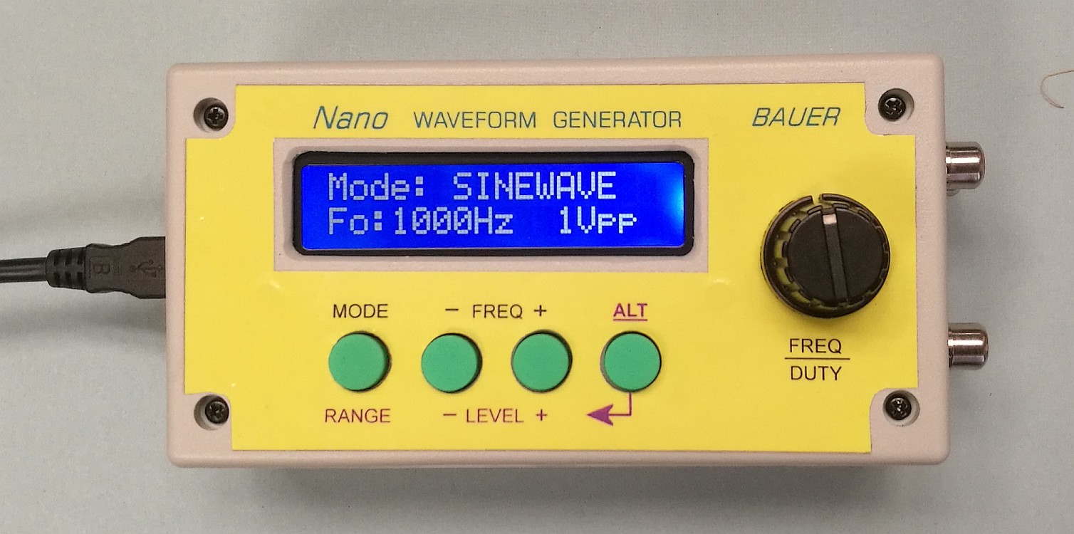
Nano Waveform Generator Waveform generators, also known as “function generators”, have been popular DIY projects since the beginning of hobby electronics. There are numerous designs out there offering a broad range of functional features and design complexities. The “Nano” waveform generator sits near the low end of complexity and build cost in the hardware design. However, it packs a lot of punch into an 8-bit AVR micro-controller to produce a useful instrument for testing audio and low-speed digital equipment.
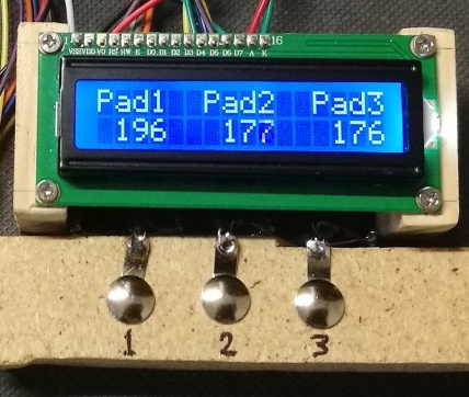
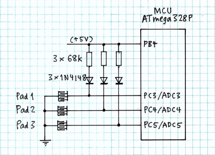
View/Download Design & Contruction Notes Download Firmware Development Kit (source code, hex file, project files) View/Download PCB design here (single-sided for easy DIY) There is also a double-sided PCB design (Gerber files available... send email inquiry) ___ Capacitive touch-pad sensing on any micro-controller Some MCU devices provide “automatic” measurement of capacitance between an I/O pin and earth (GND) to facilitate touch-pad sensing. However, a change in capacitance on an input pin can be detected quite easily without any special on-chip wizardry. The technique described in this note uses only one resistor and diode for each touch-pad input. The software algorithm is short, ensuring minimal processing overhead.
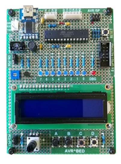
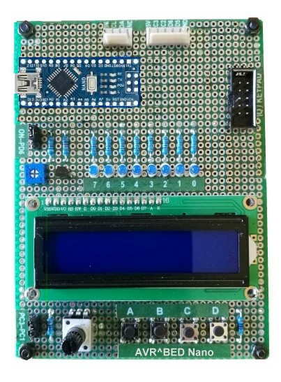
Building your own micro-controller development board will not only improve your workshop skills, but the completed product will serve well as a hardware platform for learning embedded programming skills. The "AVR-BED" is based on Atmel’s ATmega88PA microcontroller. An ATmega328P (as in Arduino Uno R3 and Nano boards) may be substituted if more memory is needed. The board incorporates a 2-line x 16-character LCD module, some LEDs, 4 push-buttons and a potentiometer providing a 0..5V analog signal source. To
make construction even simpler, an alternative design is based
on
the Arduino Nano board (v3).
The download pack contains detailed design and construction notes, a peripheral function library, plus a "test and demo" program. Sample code was developed with AVR GCC under Microchip/Atmel Studio IDE (v7). Download AVR-BED Distribution Pack (zip) How to load program code into an Arduino Nano (or Uno R3) board without Arduino IDE Embedded C Programming Tutorial for novices Here is a self-study tutorial intended as a first course in embedded microcontroller programming using a sub-set of the C language called “C-less” (C language essentials). C-less was conceived to provide enough of C to develop “real-world” applications, while avoiding unnecessary complex constructs which novices might find overwhelming.  The
software development environment used in this tutorial is
Microchip/Atmel
Studio IDE for AVR and SAM Devices. This is a free download from
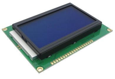
Microchip’s website. The Tutorial has a companion "C-less Reference Manual". View/Download AVR Embedded C Tutorial View/Download C-less Reference Manual Download Tutorial Example Programs ___ Graphics Function "Library" for Monochrome LCD and OLED Modules This software package is designed for monochrome (1 bit-per-pixel) graphics LCD modules with a display format of 128 x 64 pixels. The package includes device drivers for GLCD modules based on the KS0107/KS0108 controller chipset or ST7920 chip. Also included is driver code for the SH1106 OLED display controller. Suitable GLCD and OLED modules are sold by Adafruit and Sparkfun. Compatible modules may be available at lower cost via eBay, AliExpress, etc.
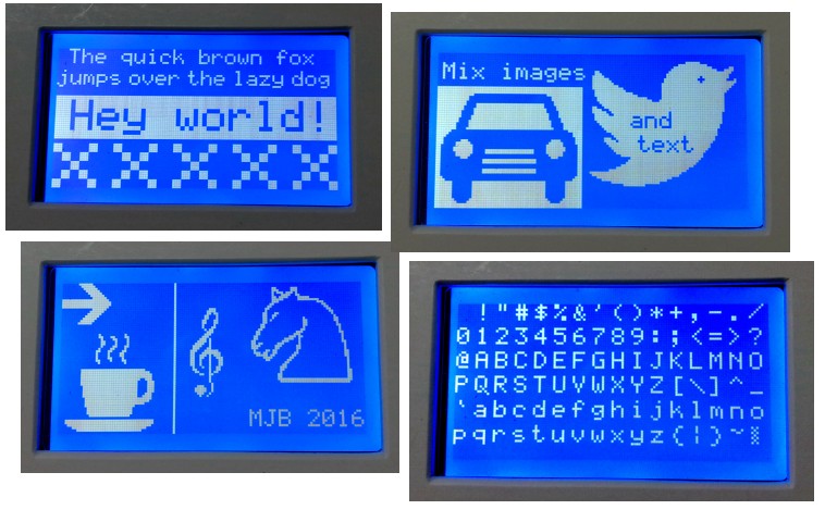
NB: The package is not a hack of the Arduino "GLDC" library! My software was developed from scratch to be simpler, easier to read, more efficient and to optimise write speeds for text and bitmap image rendering. The drivers were designed for Microchip PIC devices, but hardware dependencies are confined to low-level driver files so as to make the code easily portable to other MCU device types, e.g. ATSAMD21.
Functions provided in the LCD Graphics library:
Character font sizes
available: 8, 12, 16 and 24 pixels (char cell height, incl. descenders). The software package includes support for
Microchip's "Graphics Resource Converter" (GRC) utility. The GitHub repository (link below) includes a test/demo application with all project files required for development using Microchip MPLAB.X IDE. There is another package
specifically for 1.3" OLED display applications using the Arduino IDE. Go to GitHub repository for LCD/OLED Graphics Library ___ Generalised User Interface for Embedded Applications ... using a graphics LCD module and keypad (or touch-panel) This
article is concerned with firmware design and implementation for
microcontroller-based devices incorporating a "local" user interface
(front panel) comprising an LCD screen and keypad (or a number of
push-buttons). The technique can be extended to build a graphical user
interface (GUI) comprising an LCD screen with touch-panel. Typical
applications will have many "screens" to be presented and, for each
screen, a selection of user options for various actions, most of which
will
result in a switch to a different screen or a change in displayed
information
on the current screen. For all but the most trivial of applications,
navigation
from one screen to the next presents a challenge to the developer and
can
easily become a convoluted mess if not handled methodically...
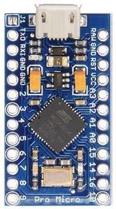
Digital Audio (PCM) Sound Effects Software Appealing sound effects may be too complex to be generated in real time by a low-end micro-controller in an embedded device. However, sound effects may be synthesized by a purpose-built application and stored as a sequence of PCM samples in a data file. Saved sound effects can be loaded into flash memory in the target embedded system for fast access by an audio player function. The storage medium is typically a "serial data flash" (SDF) memory device interfaced to the MCU via SPI. However, the micro-controller’s internal flash program memory can also hold sound FX data. PCM sound effects data files can also be produced from standard audio file formats such as WAV, MP3, etc, using "Audacity" - a free open-source audio editor application. There is a plethora of sound effects available for download on the internet. Audacity can also be used to record sounds using a microphone, CD player, sound synthesizer or musical instrument, etc. Once loaded into Audacity, audio data can be re-sampled at the required sample rate and then exported in “RAW” data format (stripped of header information) compatible with the target embedded player. The software described in this article comprises a simple sound FX synthesizer application, an audio player function and various utilities to transfer sound FX data files between the SDF memory device and a removable mass-storage device, e.g. a USB flash drive. The software was originally developed for Microchip’s PIC32MX (32-bit) micro-controller family, but could be easily customized to suit others... more... ATmega32U4 MCU Peripheral Function Library ... for use with Microchip/Atmel Studio IDE -- not Arduino!
Download Pro Micro AT_32U4 Function Library (C source code files) How to load program code into a Pro Micro module using Microchip/Atmel Studio IDE ___ Disclaimer: Source code and other "intellectual property" offered as free downloads on this website are original works of M. J. Bauer, except where acknowledged to the contrary. Otherwise, any resemblance to prior art originated or developed by others is purely coincidental, or due to derivation from similar works or well-established art in the public domain. The author does not accept liability for any adverse consequence of the use of "intellectual property" obtained from this website or respective GitHub repository. |