|
Build the "REMI 2" (EWI MIDI Controller) A DIY Project by M.J. Bauer |
||||||||||||||||||
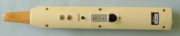
This web page describes the design and construction of the "second generation" (mk2) REMI handset.
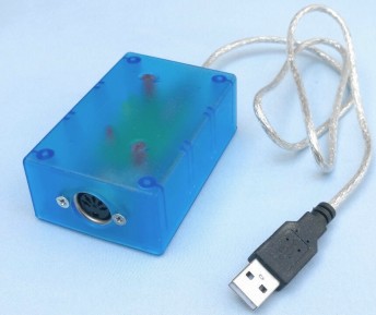
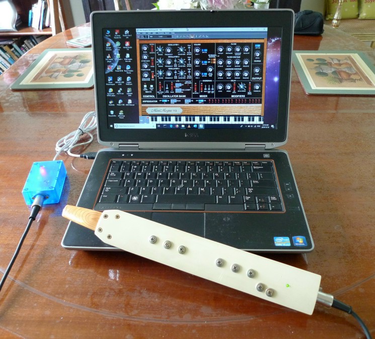
REMI 'mk2' Handset with MIDI-USB adapter box |
||||||||||||||||||
REMI 2 is an "electronic wind instrument" (EWI) with a choice of fingering schemes based on the recorder, including close emulation of modern English and German recorders. The simplified generic REMI fingering is designed to be easier to learn, for beginners with no previous experience of wind instruments. REMI 2 is
simply a MIDI controller with standard MIDI OUT connection (5-pin DIN
socket). It does not have a built-in sound synthesizer, so it must be
plugged into an external MIDI sound module or synthesizer having a
classic MIDI IN socket. A simple cable "breakout" adapter is required for "Power-over-MIDI" to supply 5V DC to the REMI handset via the DIN-5 connector. A low-cost MIDI-USB adapter (under $10) allows the REMI to be used with a "virtual synthesizer" (software application) running on a computer or mobile device. The photo above shows the REMI connected to a laptop running the free "Mini-Mogue VA" (virtual analogue) synth app. There are many other freeware "virtual synth" app's available. (There are much better ones available at a price!) The REMI can also control a modular analogue synth via a MIDI-to-CV translator (adapter module). REMI 2 Features
A configuration setting called “Pitch Offset” is provided so that the range of musical notes produced by the REMI can be shifted, i.e. transposed, up or down by a number of semitones. Five special cases shown in the table below allow the REMI to emulate a variety of recorder types:
A USB/serial port allows a host PC to be connected to the REMI for setting up and testing. REMI firmware includes a command-line user interface (CLI) which is accessed using a "terminal" app (e.g. PuTTY) running on the host PC. CLI commands are provided for setting configuration options and for running diagnostics, etc. REMI 2 provides a facility to select one of 8 instrument presets directly from the handset, without needing to use the synth control panel. The desired preset is selected by a button in combination with a touch-pad. MIDI Program Numbers corresponding to the 8 REMI presets can be set up using a CLI command. For complete descriptions of REMI features, e.g. the CLI, fingering schemes, configuration options, hardware testing, sensor calibration, instrument presets, etc, please refer to the REMI 2 User Manual. ___Touch-pad Layout and Fingering Schemes There are two pad layout options to choose from. The firmware has a
configuration parameter allowing selection of either option. The
physical layout of touch pads for each of the two options is shown
below.
___
_ The first option (top picture) is more reminiscent of a recorder and should appeal to existing recorder players. Use this layout if you opt for a fingering scheme which emulates an acoustic recorder. The second option is more abstracted from the recorder. An extra pad (LH4) operated by the left-hand little finger is added, but overall it's a simpler scheme which is compatible with some of the commercial EWIs. Details of supported fingering schemes can be found in the REMI 2 User Manual. Recommended Baroque (English) recorder fingering chart compatible with the REMI 2: |
||||||||||||||||||
| Handset Design
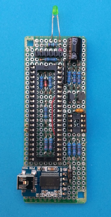
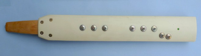
The REMI 2 handset design is based on a low-cost 8-bit microcontroller (PIC18FxxK22) with capacitive touch-sense inputs for the touch-pads. The REMI has a classic MIDI OUT connection (5-pin DIN) with "Power-over-MIDI", compatible with the 'MIDI IN' socket on the ItsyBitsy M0 Synth Module. The MIDI IN connector on the IstyBitsy M0 synth supplies 5V DC power to the handset. The REMI can connect to other MIDI sound modules, or to a computer, via a simple DIY MIDI-USB adapter module. The microcontroller board has a USB-serial bridge (FTDI FT232RL breakout board) allowing the handset to be connected to a PC running a terminal emulator app (e.g. "Putty"). The USB/serial "service port" provides a command-line user interface (CLI) to facilitate setting up and testing handset operation. Construction The prototype handset was made from two pieces of PVC plastic cut from a scrap of drain pipe, 110mm outside diameter, 3mm wall thickness. A suitable scrap may be found perhaps on a building site. The curved surface makes the plastic covers very rigid and strong. The upper piece has 3 wooden "ribs" (8~12mm thick) glued to it, allowing the bottom cover to be attached with self-tapping screws. Side strips of thin timber are glued to the ribs. The plastic surfaces are not painted, but rubbed with fine abrasive cloth (P400) to give a smooth matte finish. The result is a very "retro" (1950's) look and feel.
|
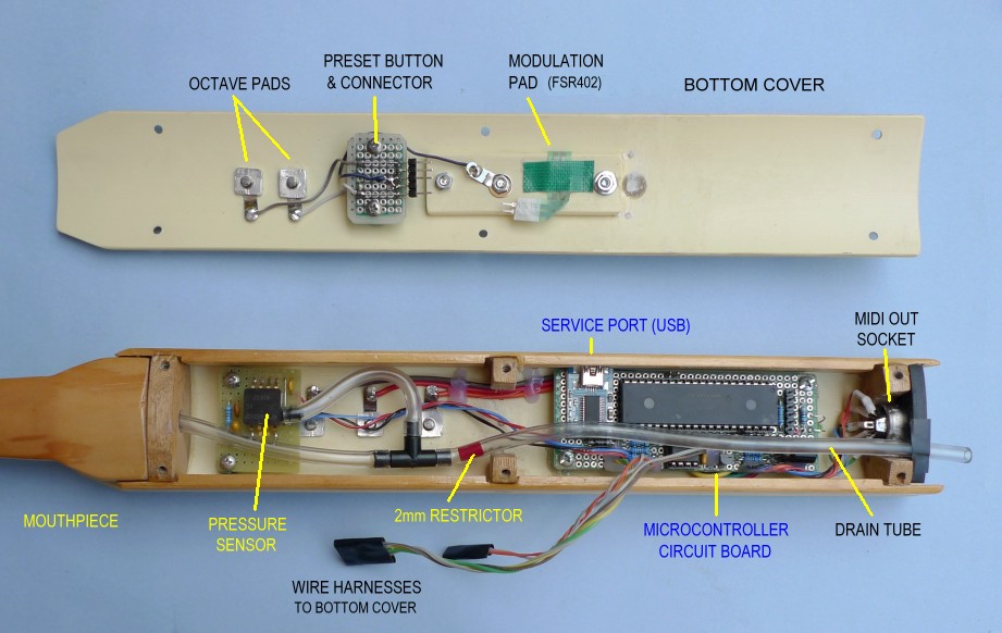
REMI handset mk2 -- Internal parts layout
The touch-pads
are self-tapping screws with a broad flat head, cadmium-plated (I
think). These are inserted
through holes in the handset playing
surface, fastened on
the inside with aluminium retainers (~9mm square). Addendum (2022): Chicago screws, as used for leatherwork, book-binding, etc, make excellent touch-pads. These are available in a variety of metal finishes incuding brass, nickel, gun-metal, stainless-steel, etc. Size required is 4mm (shank length) x 10mm diameter head. Available online at low cost. (Try AliExpress!)
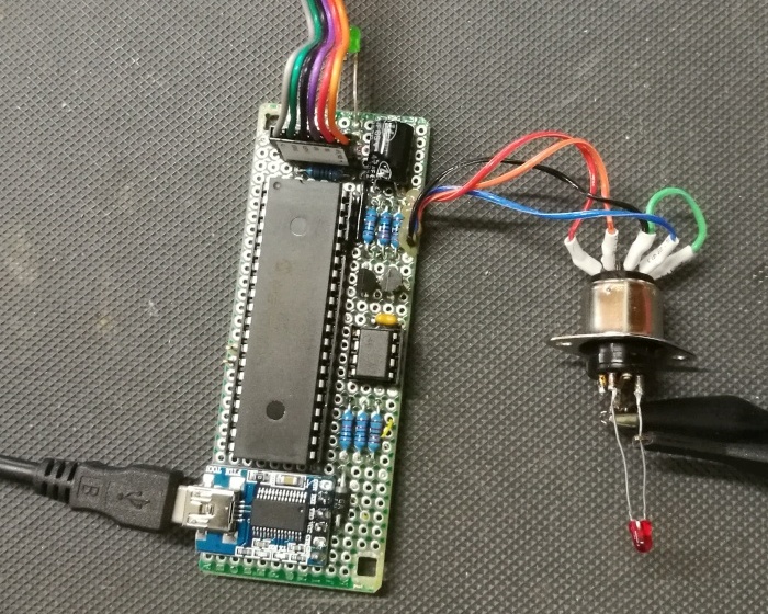
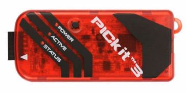
The mouth-piece is carved out of soft-wood with a 6mm hole drilled through the middle. It should be coated with a water-based sealer* to prevent moisture absorption in the wood. The nylon tubing is inserted into the 6mm hole, all the way through to the tip, and held in place with a water-based sealer. The mouth-piece is attached to the upper plastic cover with 4 self-tappers, so that it is easily removeable. *Warning: Do not use a paint or laquer with oil-based solvent on the mouthpiece, for 3 reasons... (1) it tastes terrible, (2) it could cause a health hazard, and (3) the vapours given off by the solvent could damage the Fluoro-silicone membrane in the pressure sensor. Recommended coating for the mouthpiece is water-based polyurethane or some other safe product used to varnish wooden toys. Pressure Sensor “plumbing” Tubing and other bits and pieces needed to make the airways inside the handset may be sourced from the garden irrigation section of your local hardware store. The prototype handset (pictured) used clear nylon tubing (3mm ID, approx 5.5mm OD) for the internal airways linking the mouth-piece, pressure sensor IC and the "drain tube”. The T-joiner needed the barbs cut off to fit the 3mm tubing. The sensor air inlet barb is slightly less than 3mm in diameter, which is a wee bit too small to make a good seal with the 3mm ID nylon tube. An easy solution is to fit a short bit of 2.5mm (nominal diameter) heat-shrink tubing over the barb, shrink it with a hot air blower or whatever (taking care not to melt the sensor!), then fit the 3mm nylon tube over it. A drain tube is recommended because moisture condensation occurs inside the airways and it is probably sensible to provide an exit for the moisture. Also, the drain tube allows air-flow, which is preferable to a sealed system for playability. However, the exit air flow needs to be restricted somewhat to produce a sufficient range of pressure inside the sensor. This can be achieved by fitting into the drain-tube a small plug with a 2mm hole through it, perhaps cut from a bit of plastic insulation sleeving if you can find some of suitable size (3mm OD, 2mm ID). The best place to fit the restrictor is close to the T-joiner, to minimise moisture condensation. It is also recommended to mount the pressure sensor above the T-joiner, i.e. close to the mouthpiece, to prevent moisture from accumulating in the sensor, as shown in the picture above. Modulation Pad The simplest option is to use a force-sensitive resistor (FSR-402). This will give a uni-polar output, which is not ideal for a Pitch Bend controller, but quite satisfactory as an "Effect Controller" (e.g. vibrato depth, timbre modulation, etc). The FSR is mounted behind a round cutout in the bottom cover of the handset. A plastic "backing support", made from the same material as the covers, is screwed to the inside of the bottom cover. A piece of black PVC insulation tape is stuck over the top of the FSR402 to keep it in place. The right-hand thumb pushes the FSR against the backing support. Note: The FSR402 is fragile. Take care not to damage the flex strip. Don't bend it too tightly. Insert thin washers between the handset body (bottom cover) and the FSR support piece to prevent the FSR edges from being compressed hard. The sensitivity of the Mod Pad can be adjusted using a CLI setting. If it is still too sensitive, the value of the resistor in series with the FSR-402 may be reduced. Recommended minimum value is 1k ohm. A better option for a Modulation control, assuming your workshop skills are adequate, is to make a lever mechanism, also operated somehow by the right-hand thumb. The lever position can be transformed into a control voltage (input to the ADC) using an optical proximity sensor device, e.g. CNY-70 or similar. 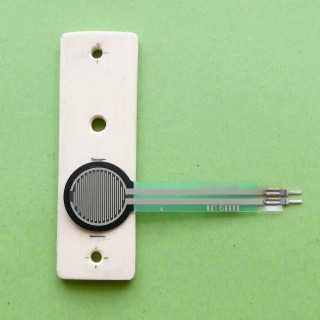 Modulation Pad (FSR402) resting on its backing support piece Electronics The handset microcontroller circuit board is constructed on a piece of prototyping board measuring 90 x 35 mm. A 40-pin DIL socket for the PIC18F45K22 MCU chip takes up most of the board area. A 6-pin SIL header for connection of the MCU programming tool (PICkit 3) is located at the top end of the board. The USB-Serial bridge (FT232RL breakout board) is located at the bottom end of the board. The MIDI transmitter and analogue sensor signal conditioning components (LM358, etc) are placed beside the MCU socket.
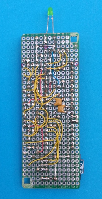
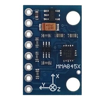
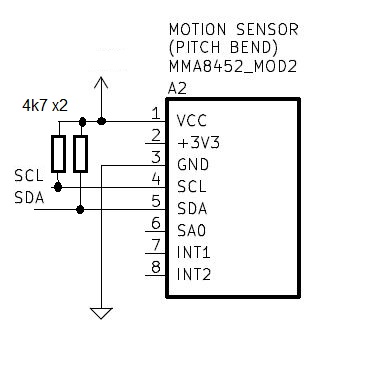
The picture above shows the MIDI OUT socket wired to the MCU board. The socket has a plug inserted with a LED wired between the OUT+ and OUT- pins. An oscilloscope was used to test the performance of the MIDI transmitter circuit, in particular for compliant rise and fall times in the output signal. The USB "service port" provides diagnostics for hardware testing. The USB/Serial bridge (FT232 breakout board) supplies 5V power to the REMI MCU (PIC18) when using the "service port" CLI, so there is no need to plug in a MIDI cable at the same time. There are many different types of USB/Serial modules available. Be sure to buy a device that outputs 5V on the Vcc pin and has 5V logic levels on the TX and RX signal lines. (Some devices are configurable for either 5V or 3.3V operation.) Note: These pictures are provided as a rough guide to makers intending to build a REMI handset. Don't rely on the photo of the underside of the board as a guide to wiring. It's best to follow closely the schematic diagram (see download links below) and check your wiring carefully before applying power. It is also recommended to test MCU board operation before wiring it into the handset (as shown in the above photo). After soldering leads to off-board parts, e.g. MIDI socket, pressure sensor, modulation pad, PRESET button and touch-pads, apply hot-melt glue to the board around the entry points of leads to prevent them from breaking off. Breath Pressure Sensor The pressure sensor is mounted on a separate little board located very close to the mouthpiece. The air inlet port should face away from the mouthpiece, i.e. downward, to prevent moisture from entering the sensor. The sensor type fitted in the REMI prototype is a MPXV5010-GP, but this part is now expensive (~US$30) and may be hard to obtain. There are other options for the pressure sensor, easier to find and at lower cost. For example, a low-cost pressure sensor with integrated electronics - XGZP6857A - is now available from online suppliers (AliExpress). The device comes in a range of maximum pressure values; 5 kPa is ideal for an EWI breath sensor (part number: XGZP6857A-005). The output voltage is suitable for direct feed to an ADC input. No external signal conditioning required! Be sure to order the part type with 5V supply voltage (Vcc = 5V). View/download XGZP6857A data-sheet If you want to try something more radical, it is possible to make a breath (air-flow) sensor using a moveable membrane and an optical proximity sensor device, e.g. CNY-70. The idea is to deflect the membrane by blowing air through a hole in the mouthpiece. The opto sensor detects a small movement in the membrane, up to about 6mm. There is a YouTube video showing a simple EWI with a mouthpiece made from the neck of a plastic bottle and a membrane made from a piece of a party balloon and a CNY-70 proximity sensor. Google "KLIKsophone".No doubt, a more elegant mouthpiece could be designed using a similar optical sensor mechanism. Whatever your choice of breath sensor, the essential requirement is to produce an output signal of sufficient magnitude to feed into an ADC input on the micro-controller. The ADC input voltage span, i.e. difference between minimum and maximum pressure, should be about 3V ideally, but must be at least 1 volt. The voltage at minimum pressure (no air-flow) should be well below 1V. In any case, be sure not to exceed the maximum allowed voltage on the MCU ADC input. Instructions for hardware testing and sensor calibration are given in the REMI 2 Handset User Manual. Pitch Bend Sensor (option) The REMI 2 firmware supports Pitch Bend capability using a motion sensor IC, MMA8451 (or -8542) 3-axis accelerometer. Suitable MMA8451/52 breakout modules are available on AliExpress for about AU$1.50 (under 1 euro!). The firmware adapts itself automatically to support either the MMA8451 or MMA8452. The motion sensor measures the tilt, i.e. angle of the handset, while a note is playing. Any change in tilt position from the start of a note will cause a change in pitch, up or down, assuming of course that the connected synthesizer responds to MIDI Pitch Bend messages. Pitch bend range and sensitivity are determined by the synthesizer... not by the REMI handset. Pitch Bend (MIDI messages) may be enabled or disabled by setting a configuration parameter in the handset (using the CLI). Hardware additions for pitch bend are very easy... only 4 wires are needed to connect the MMA8451 module to the PIC18 MCU, as shown in the diagram below. The 4.7k pull-up resistors on SCL and SDA pins are not necessary... the breakout module will have pull-ups already fitted. Vcc pin is connected to +5V. Caution: Some modules may have different pin ordering, but the signals are the same.
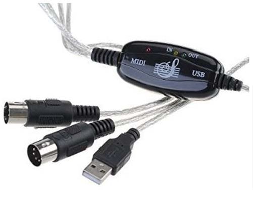
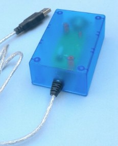
The sensor module should be mounted "upside-down", i.e. with the MMA8451 chip facing the bottom cover of the REMI handset. The module may be mounted on top of the PIC18 MCU chip using double-sided adhesive foam tape. If the sensor module is mounted so that it faces the top cover of the handset (8 touch-pads), then the pitch bend direction will be reversed, i.e. an upward tilt will result in lower pitch. The REMI MIDI-USB adapter is simply a commercial device re-fitted and re-wired into a new housing. The adapter pictured below is readily available at very low cost (under A$10) from online suppliers.
The original adapter casing can be easily broken apart by cutting around the join with a hacksaw or utility knife, taking care not to damage the circuit board inside. The two MIDI cables with DIN-5 plugs on the end are unsoldered from the circuit board and discarded. The USB cable and connections are kept intact.
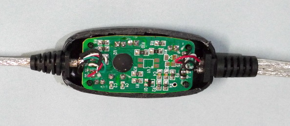
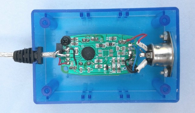
The circuit board is removed from its casing and mounted in a small plastic box together with a 5-pin panel-mount DIN socket for MIDI input (from REMI 2 or other MIDI controller). Plastic standoffs are glued into the box to hold the circuit board in place. A translucent box was chosen to allow the LED indicators to be visible through the top of the box without needing to drill holes for them. A complete MIDI-USB adapter is pictured below. This photo shows a minimal build, without MIDI THRU and MIDI OUT connectors.
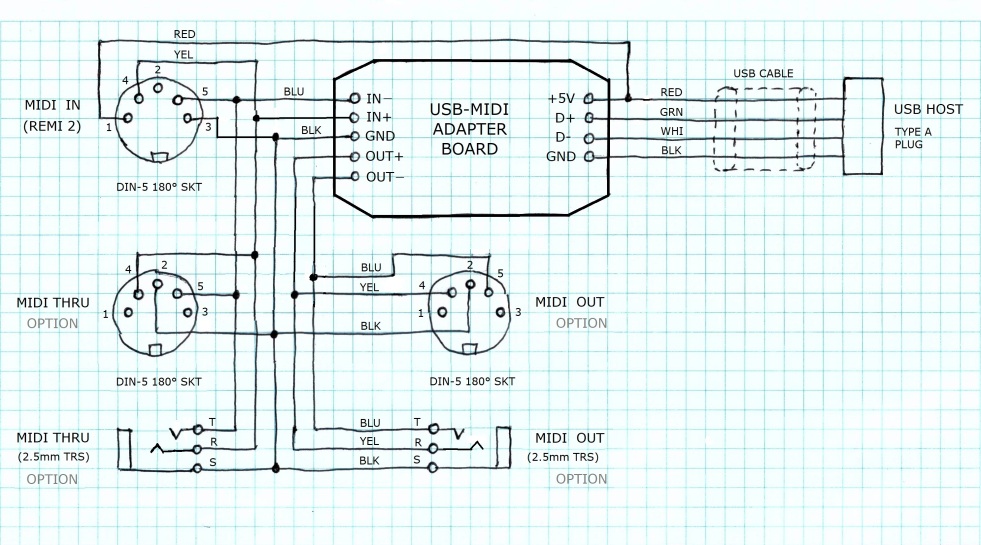
The MIDI 1.0 Specification (v4.2, 1995) states that pins 1 and 3 of the DIN-5 connector are not allocated for any particular purpose. The REMI MIDI-USB adapter uses pins 1 and 3 on the MIDI IN connector to supply 5V DC power to the REMI 2 handset. Similar "Power over MIDI" schemes are used by various commercial manufacturers, including Arduino, for their "MIDI shield" to supply 5V to MIDI devices. I decided to use the same pin allocations as Arduino, i.e. pin1 = +5V, pin3 = 0V (GND). Beware: Other MIDI device manufacturers use different (incompatible) pin allocations and voltages, e.g. pin1 = GND, pin3 = +12V, pin3 = +24V. The USB cable on the MIDI adapter supplies power to the REMI from any regular 5V USB power pack (phone charger) or from a host computer. The circuit diagram below gives wiring details for the adapter. The diagram also shows connections for optional 'MIDI THRU' and 'MIDI OUT' sockets. These may be DIN-5 types, and/or 2.5mm "micro" TRS types, as fitted on some low-end mini synthesizers. Provision of a MIDI THRU socket allows the REMI to operate with any synth having a MIDI IN connector. Provision of a MIDI OUT socket allows the adapter to connect a computer to an external synth with a classic MIDI input.
If you only want MIDI IN (for REMI handset) and USB for host computer or USB synth, then you don't need to house the parts in a new box. You could use the original adapter casing. All that needs to be done is remove the two MIDI cables and add a new MIDI IN cable with 5-pin DIN plug for the handset. You could also add a MIDI THRU cable with inline DIN socket, if you want to connect your REMI to a hardware synth module with MIDI IN. The adapter casing can be joined back together with black PVC tape. NB: A standard MIDI connection requires only pins 4 and 5 to be wired. Some
ready-made MIDI cables may have only 2 cores inside (plus screen = pin 2). Be sure to buy (or make) a MIDI cable with all 4 cores (plus screen) to connect your REMI 2 handset to the MIDI-USB adapter. Firmware The REMI firmware maintains a bunch of user-settable “configuration parameters” allowing it to function properly with a variety of MIDI-controlled sound modules and synthesizers, whether hardware or software. Some parameters define the physical properties of the handset, for example, the touch-pad layout and fingering scheme. Other parameters are provided for calibration of the breath sensor and modulation pad. Duplicate sets of configuration parameters are provided so that it is quick and easy to switch control between two of your favorite synthesizers or sound modules. The required synth parameter set is selected by the 'Mode' switch. Provision of a 'Mode' switch is optional. If your REMI omits the switch, it is recommended to tie the switch input pin to GND. Configuration parameters are stored in non-volatile memory, so their values will be preserved when the REMI is powered off. Be aware that after a firmware update, however, all parameters will revert to default values, so it will be necessary to re-enter any different values required for your particular REMI and synth setup. Service Port CLI The REMI provides a "command-line user interface" (CLI), accessed via a computer connected to the USB "service port" (FT232 USB/serial bridge) on the REMI micro-controller board. The host computer needs a terminal emulator program (e.g. "PuTTY") installed. Various CLI commands are provided to view and set configuration parameters, to view and set instrument preset assignments and for hardware testing, sensor calibration, etc. Details of service port CLI operation are given in the REMI 2 User Manual. Programming Tools A PIC programming
tool, e.g. Microchip PICkit-3, is required to install the REMI
application firmware.
REMI
firmware is built using Microchip PIC development tools - MPLAB.X IDE
with XC8 compiler - free to download from Microchip's
website. If
you intend to modify or extend the firmware, you will need these tools.
Otherwise, you just need to install the PIC programmer application
(IPE) on your
computer. Please refer to Microchip documentation for instructions to use the programming tool. |
||||||
Disclaimer: The REMI is not a commercially available product. The hardware design and software source code are in the public domain. The design may be replicated by suitably skilled electronics hobbyists. Detailed step-by-step instructions and parts lists are not provided. The information published here may be used as a basis on which to design your own customized EWI. If you are interested in building a REMI and/or if you have enjoyed following the project here, kindly send me an email. Technical support is offerred to readers who wish to build a REMI or similar EWI controller.
See MJB's Index Page Last update: March 2024 +++ |