|
ItsyBitsy M0 Synth | Sigma-6
Voice Module A DIY project by M.J. Bauer |
||||||||||||||||||||||||||||||||||||||||||||||||||||||||||||||||||||||||||||||||||||||||||||||||||||||||||||||||||||||||||||||||||||||||||||||||||||||||||||||||||||||||||||||||||||||||||||||||||
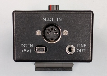
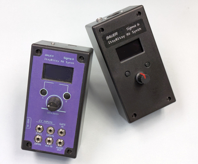 ItsyBitsy M0 synth stand-alone module -- with CV input jacks (left) -- and without CV inputs (right) |
||||||||||||||||||||||||||||||||||||||||||||||||||||||||||||||||||||||||||||||||||||||||||||||||||||||||||||||||||||||||||||||||||||||||||||||||||||||||||||||||||||||||||||||||||||||||||||||||||
|
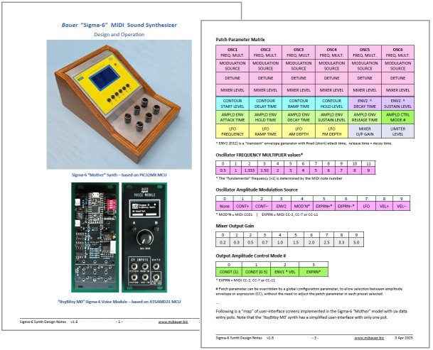
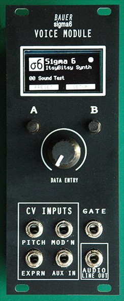
This project is a simple-to-build, low-cost digital mono-synth which I call the "ItsyBitsy M0 Sigma-6". The design is based on Adafruit's SAMD21 "ItsyBitsy M0 Express" micro-controller board. You can substitute a dirt-cheap compatible MCU board (RobotDyn 'SAMD21 M0-Mini') available on AliExpress. Don't be fooled by the simplicity of the hardware... the firmware implements a complex sound synthesizer comprising 6 oscillators, mixer, 3 envelope shapers, LFO with ramp, variable-gain attenuator (DCA), plus overdrive and reverberation effects. The firmware includes a diverse range of instrument sounds (presets). With two or more "Sigma-6" modules, you can play multi-part music using a MIDI sequencer. Sound quality is excellent using a 12-bit DAC, 32kHz sample rate and 32-bit precision DSP computations. The tone-generator algorithm is immune to aliasing effects (except when overdrive is enabled). You can build a minimal version comprising little more than the SAMD21 MCU board, audio DAC and a MIDI input circuit, or a more elaborate version with a small control panel (OLED display, 2 buttons and a knob). The 'full-featured' build is a 3U rack-mount module with CV and GATE inputs to realize a pseudo-analog "voice module". A group of Sigma-6 voice modules can be connected via a MIDI bus to a "master controller" board to make a respectable polyphonic synthesizer ... More about that here. The synth software is compiled using the Arduino IDE, so if you have C programming skills, you can easily modify and extend the (open-source) program to suit your own requirements. Details of the 'Sigma 6' synthesizer concept, design and operation can be found in this PDF document...
Examples
of Sigma-6 Synth build options:
___ Sample Sound Clips
'Two-part Invention' (J.S. Bach) - Duet for 2 Sigma6 synth's, played by a MIDI sequencer. 'The Model' (Kraftwerk) - Produced using PreSonus 'Studio One' Prime v5 (DAW) driving 2 Sigma6 modules. The drum sounds are made with Studio One soft-synth 'Presence'. 'Promenade' (by Jean-Pierre Meyer) - Produced using a MIDI sequencer app driving six Sigma-6 modules, this clip demos a few of the many different instrument sounds (presets) available. 'Variations #1' (by JPM) - More presets in this 4-part sequernce 'Song 1' (by JPM) - Sequence produced in 'CV
Mode'
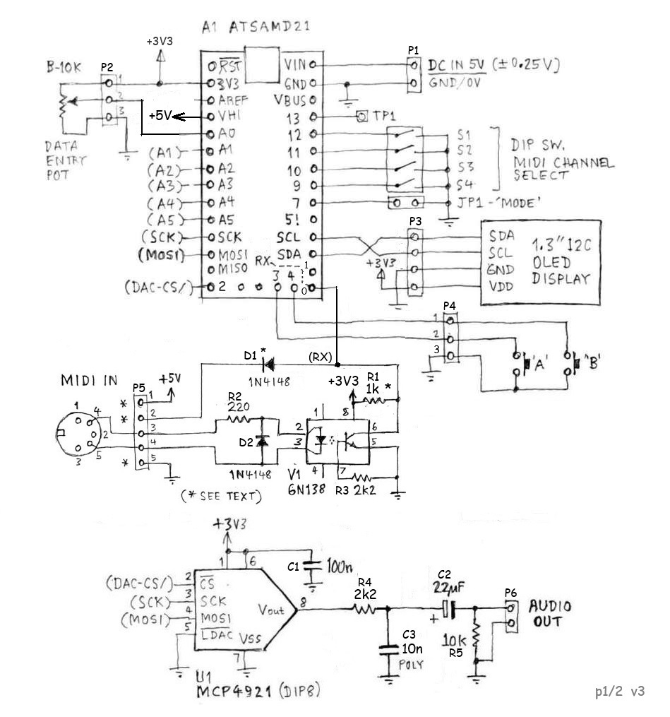
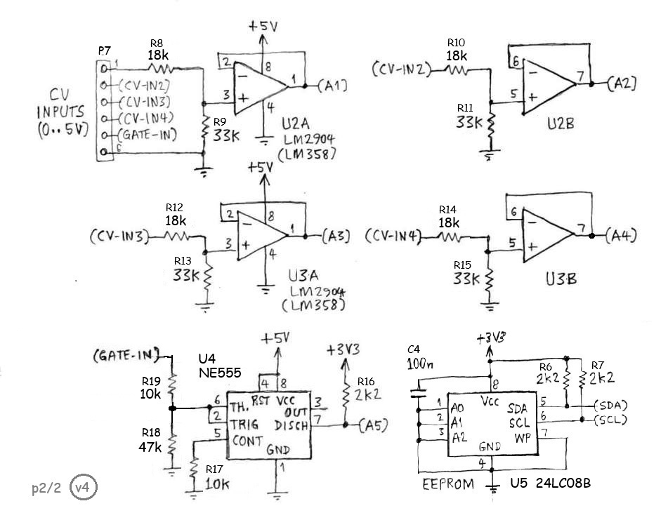
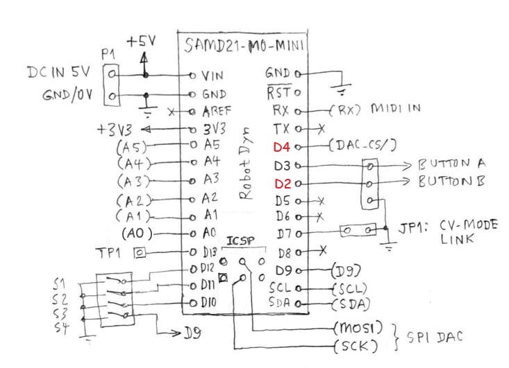
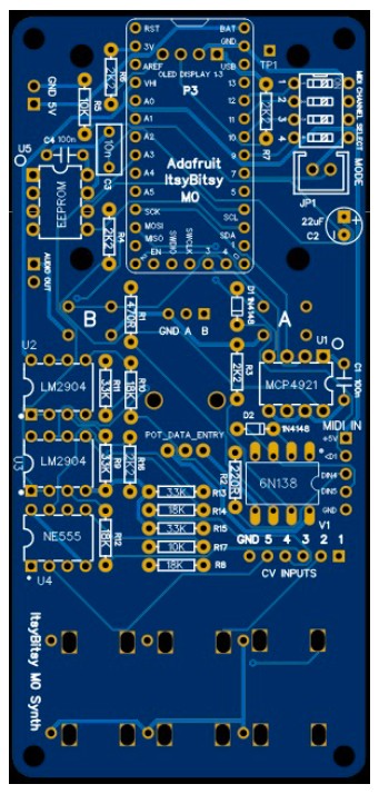
___ Circuit Design Here is the schematic of the ItsyBitsy M0 Synth circuit board. The control panel comprising OLED display, 2 buttons and 'data entry' pot is optional, depending on your intended usage. Hardware variants requiring analog (CV) inputs will need additional components fitted, shown in part 2 of the schematic below.
SAMD21 ADC inputs are 3.3V full-scale. The external CV inputs are scaled to accept a 0 to +5V signal range. The op-amp buffers ensure that the voltage at the ADC inputs cannot exceed +3.5V, or go negative. The LM2904 and LM358 have a common-mode input range 0 to +3.5V provided Vcc = +5V. The op-amps also allow a high input resistance (50k ohm) at the external CV inputs and a low source resistance feeding into the ADC inputs, as required. The GATE input is fed into a 555 timer IC which is not wired as a timer, but as a Schmitt Trigger to ensure glitch-free transitions. With Vcc = 5.0V, the upper input threshold (VH) is about 2.5V; the lower threshold (VL) about 1.25V, which is 5V logic compatible. The 555 "discharge" output is open-collector which makes a simple 5V to 3.3V level translator using a pull-up resistor. A
low-capacity I2C EEPROM (24LC08B) should be fitted for storage of
persistent data, independent of the SAMD21 MCU which loses its marbles
every time a firmware update is done. The EEPROM is
optional. User
preferences, configuration
parameters, CV1
calibration constant, etc, can be hard-coded into the
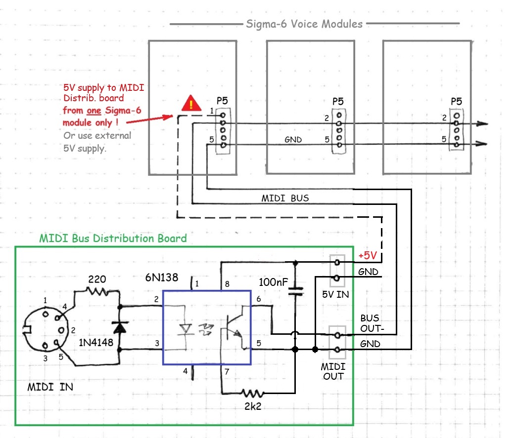
firmware. MIDI Input and MIDI Bus Scheme There is a choice of MIDI IN circuit configurations. The opto-coupler (V1) is optional, but recommended for applications where only one Sigma-6 synth module will be connected to a MIDI controller. The MIDI IN circuit was designed with a view to connect multiple modules to a common MIDI bus. For these applications, the opto-coupler (V1) may be omitted. The common bus connection is pin2 of header P5 (and GND of course). Pull-up resistor R1 should be 1k ohm (marked 470 on PCB rev1). The MIDI bus scheme requires a simple "MIDI distribution board" having a standard opto-isolated MIDI IN receiver circuit with an open-collector output, as shown in this schematic...
Note:
It is easily doable to modify one of your Sigma-6 modules to
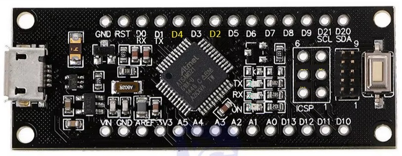
serve as the 'MIDI distribution board'. Low-cost SAMD21 MCU alternative A cheap ATSAMD21 breakout board may be used instead of the Adafruit 'M0 Express' board. These are available on AliExpress using the name "SAMD21 M0-Mini", designed by 'RobotDyn'. Although the RobotDyn board is not physically compatible with the Adafruit 'IstyBitsy M0', all of the required I/O pins are accessible. Annoyingly, pins D2 and D4 are reversed relative to the Adafruit M0 and Arduino Zero. This irregularity is fixed in the program code, but in hindsight, would be better fixed in the circuit design. This picture shows the signal pin assignments for the "SAMD21 M0-mini" board...
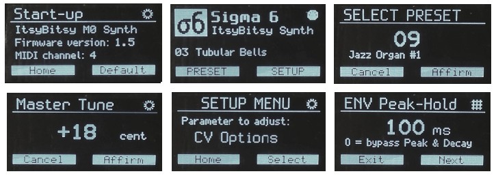
___ Control Panel - User Interface The control panel allows selection of presets, of course, and setting of configuration parameters, plus adjustment of some patch parameters. The selected preset determines the basic sound characterstics. It is not feasible to allow all (42) patch parameters to be adjustable with such a simple user-interface... two buttons and a knob! However, the ability to adjust parameters for the oscillator mix levels, amplitude envelope, LFO (vibrato) and audio overdrive from the front panel, provides essential variability of sound characteristics.
Most of the synth configuration parameters and many patch parameters are also settable via MIDI messages. (Refer to the section "MIDI Implementation" for details.) To adjust the display brightness, turn the knob while viewing the 'Home' screen. The last setting is remembered. New features added in firmware v2.8 + v3.0: MIDI channel selection can be done via the control panel (SETUP menu) for synth variants with OLED display and EEPROM fitted. Otherwise, the channel defaults to the DIP-switch setting. The SETUP menu has an option "Keying Mode" which allows you to switch between "Multi-trigger" and "Legato" modes of operation. There is also a MIDI message type (CC68) which does the same thing. There is now an "EWI auto-detect" function to set the keying mode and audio amplitude control automatically to suit EWI controllers. If a MIDI 'Breath Pressure' message (CC02) is received, the keying mode is set to "Legato" and the audio ampld control mode is set to "Breath Control" (CC02). If you are using a MIDI controller other than an EWI, e.g. a MIDI keyboard or sequencer, be sure to set the Audio Amplitude Control mode parameter to "ENV1*VEL" (envelope with velocity). Changes to 'Keying Mode' and 'Audio Amplitude Control' are temporary. These settings will normally revert to their respective configuration parameters (loaded from the EEPROM) on start-up. However, if you change another config parameter and save it to EEPROM, then the current settings of 'Keying Mode' and 'Audio Amplitude Control' will be saved to the EEPROM as well. Oscillator Mix Levels are now adjustable using the Control Panel. Select 'Mixer Levels' from the Setup menu. To exit the Mixer Levels screen, press button A. To select the next oscillator for adjustment, press button B. The selected oscillator number (high-lighted on top row) will flash. The mixer levels are shown on the bottom row. 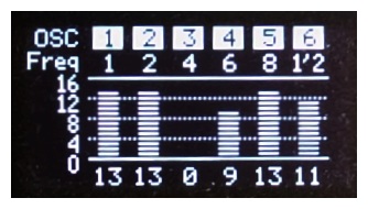 'Mixer Levels' screen -- The frequency of Osc. #6 is 1/2 x fundamental ... Multi-trigger and Legato Operation The ItsyBitsy M0 synth complies with the MIDI Specification 1.0 for monophonic devices with respect to Legato operation. However, if 'Legato Mode' is disabled and the attached MIDI controller (keyboard, sequencer, or whatever) operates in POLYphonic mode, then the synth functions as follows... Regardless of a note already playing, if another Note-On event occurs (e.g. a key is pressed), then the new note is initiated with envelopes in the 'attack' phase. The note playing is terminated with envelopes in the 'release' phase when a 'Note-Off' event occurs with the same note number as that used to initiate the note. If a note is already playing (key held down) when a new note is keyed, the note playing will be terminated before the new note is initiated. This is also known as "Multi-Trigger" mode. If 'Legato Mode' is enabled, OR if the attached MIDI controller (keyboard, sequencer, EWI, etc) operates in MONOphonic mode, then the Sigma-6 synth functions as follows... If
a note is already playing (key held down) and a new note is keyed, the
pitch of the note playing will change according to the note number of
the new note. However, the envelope generators will be unaffected...
there will be no "repeat attack". If the last note keyed is released
before the first note keyed, then the pitch changes back to the first
note, but again there will be no "re-attack".
Only when the first note is terminated (all keys released) will the
envelopes enter the "release" phase. A subsequent Note-On event (key
press) will cause the envelopes to enter the "attack" phase, of course. Presets 32 ~ 63 ... Explanation of Nomenclature The names given to "factory" presets 32 thru 63 are based on patch parameters which are not settable via the control panel user-interface. The first word in each preset name is a colour. The colour indicates the combination of frequency multipliers assigned to the six oscillators, as shown in this table:
Values shown are frequencies relative to the fundamantal frequency of the note. These numbers also represent the harmonic order. For example, a value of 3 represents the 3rd-order harmonic. Of course there are many other possible combinations of harmonics and sub-harmonics. You can experiment with various combinations by modifying existing presets or by adding your own presets in the program code. The output amplitudes of the six oscillators, i.e. the mixer input levels, are settable via the front-panel user-interface. The sound characteristic (timbre) of a preset can be varied dramatically by adjusting the relative oscillator levels. Tip: It can be rewarding, when attempting to create a new sound, to begin with just 2 or 3 oscillators in the mix. Following the colour in each preset name is a mnemonic string indicating the source of modulation of one or more oscillators. If there is no modulation applied, the text "No Osc AM" appears. If the mnemonic "Modn" appears, it means that one or more oscillators can be modulated by MIDI Modulation messages (Control Change 01). The modulation depth is determined by the respective Oscillator Mix Level(s). Other preset provisions are modulation by the Contour envelope generator or by the "Transient" generator (ENV2/EG2). Any oscillator(s) affected by a modulation source are shown in the preset name. Lastly, the word "detune" may appear, indicating that some oscillators in the group are detuned relative to others. As noted earlier, preset/patch parameters associated with the low-frequency oscillator (LFO), Amplitude Envelope (ENV1) and Overdrive (Mixer Gain and Limiter Level) are settable via the user interface, so you can experiment ad lib with these settings. When you are satisfied with a new sound you have created, you can make it permanent by writing it into the program code. Instructions
to add or modify a preset in the program code can be found
in this document... MIDI Implementation Channel selection via Control Panel Synth module variants with a control panel (OLED display, etc) allow the MIDI
channel to be selected via a SETUP menu option, in which case the
channel selection over-rides the DIP switch setting. The channel defaults to the DIP-switch setting if the OLED display is not fitted or not functioning, or if the EEPROM is not fitted or not responding. In any case, the selected channel is shown in the Start-up screen. Channel selection via DIP-switch settings
[ Legend: 0 = On (closed); 1 = Off (open) ] The module responds to valid messages addressed to the selected MIDI IN channel and, if MIDI mode is set to 'Omni' (switches set to 0000), it will respond to all messages received, regardless of which channel(s) the messages are addressed to. The module also responds to valid messages addressed to channel 16, regardless of the module channel setting, so that the host controller can transmit a "broadcast" message to all modules on the MIDI bus simultaneously. NB: Restart the device (reset MCU) after changing MIDI channel DIP-switch setting.___ MIDI Message Types Supported The ItsyBitsy M0 Synth recognises MIDI messages: Note-On (with Velocity), Note-Off, Program Change (= Preset select), Pitch-bend, plus Control Change messages summarized in the table below:
Note 1: If Hold Time = 0, the Decay segment is bypassed; i.e. Attack is followed by Sustain. Note 2: 0 = Use Patch parameter; 1 = Fixed (full-scale); 2 = ENV x Velocity; 3 = Expression Note 3: 0 = Vibrato Off; 1 = MIDI Modulation (CC1); 2 = CV4 AUX-IN signal; 3 = Automatic (ramp) Note 4: 0 = Pitch-bend disabled; 1 = MIDI Pitch-bend msg; 2 = CV1 PITCH signal Note 5: Registered
param 0 = Pitch-bend Range
(semitones); Reg. param 1 = Fine Tuning. Note 6: If a
polyphonic MIDI keyboard or sequencer is used to control the
synth, it will function Most
of the synth parameters settable by MIDI CC messages (70 ~ 89) are also
settable using the control panel. Configuration parameters set by CC85
thru CC89 are stored in EEPROM (where fitted) and hence are
persistent across power-downs. Parameters set by CC70 thru CC79 are
active patch parameters. These settings will default to values defined
by the preset patch, whenever a preset is selected. Analog (CV) Control Mode The
Sigma-6 "Voice Module" operates either as a
voltage-controlled or MIDI-controlled device. The control mode
is
initialized at power-on/reset according to jumper JP1 setting.
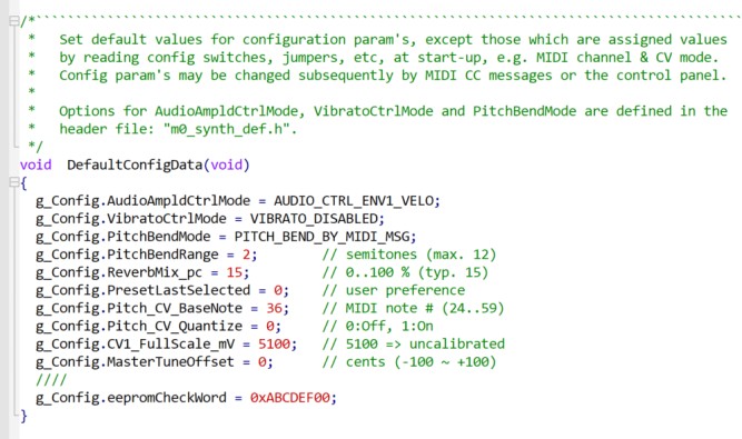
Thereafter, the software switches the mode automatically... In CV mode, oscillator frequency is set by the CV1 (PITCH) input voltage, which covers a 5-octave range. The pitch corresponding to zero volts is set by a configuration parameter 'Pitch CV Base Note', which can be modified by a MIDI message (CC85) or using the control panel (SETUP: CV Options). The default setting is note #36 (C2). Audio output amplitude is controlled dynamically, either by the synth envelope shaper (ENV1) or by CV3 (EXPRN) if using an external signal. If using CV3 to control expression, set configuration parameter 'Ampld Control Mode' to "Expression". There is also an option which allows CV3 to serve as a "Velocity" signal with 'Ampld Control Mode' set to "ENV1*Velo". With this option enabled, the CV3 input signal is sampled when the GATE input goes High. Any change in CV3 thereafter, i.e. while the note is playing, will have no effect on the audio level because it is controlled only by the envelope. The GATE signal (5V logic) controls all internal envelope shapers: the Amplitude Envelope (ENV1), "Contour" and "Transient" Envelope (ENV2/EG2). The envelope generators enter the 'Attack' phase on the GATE signal rising edge (Low to High). They enter the 'Release' phase on the GATE signal falling edge (High to Low). Refer to the "Sigma-6 Design Notes" document for details of the envelope functions. There is an option to quantize the CV1 (pitch) input signal so that the oscillator (fundamental) frequency is fixed to the nearest semitone on the chromatic scale. This may be useful if the external control voltage source is not already tuned to a musical scale, or if it is not well calibrated. Various analog sequencers and random note generators (using sample-and-hold techniques) may fall into this category. Of course, you may prefer not to have the oscillator pitch quantized, in which case turn off the 'quantize' option! If the CV option "Pitch Quantize" is enabled and the Keying Mode is set to "Multi-trigger", the CV1 input voltage will be sampled once only when the GATE signal is asserted (leading edge). The oscillator pitch will remain constant until the next GATE signal. However, vibrato (LFO FM) will function as configured. [Feature added in firmware v3.xx.] NB: Noise from the external 5V supply may affect the CV input signals. Noise on the CV1 input can manifest itself as an audible "wavering" of the note pitch, i.e. random frequency modulation. Hence, if using CV controls, be sure to use a low-noise PSU, preferably with a linear regulator. It might also help to wire a 47uF electrolytic from VIN (+5V) to GND. Max. frequency of signal fed into CV1 input Frequency modulation of the synth oscillators can be achieved by adding an AC component to the signal applied to CV1. The AC component (if any) should be band-limited (low-pass filtered) with a cut-off frequency around 250Hz; otherwise aliasing artefacts (unwanted audio frequencies) could occur. CV1 Input Calibration The 'Start-up' screen presents an option to calibrate the CV1 input. Press Button [A] within 3 seconds from start-up to invoke this function. Apply a stable DC voltage source to the CV1 input. You can use a battery (3 ~ 4.5V), or use the internal +3.3V line, or a voltage-divider on the +5V supply to obtain a voltage in the range 3 ~ 4.5V. Measure the voltage applied to the CV1 input jack using an accurate voltmeter. Call this "actual_input_mV". You could use a 3½ digit DMM (full-scale 3.999V) if the voltage source is less than 4V, but these are rarely better than 0.5% accurate on DC volts. Preferably, use a 4½ digit DMM with DC accuracy 0.1% or better. Wait a few seonds for the CV1 voltage indicated on the display to stabilize. Call this "adc_reading_mV". The ADC reading assumes CV1 input full-scale is 5100mV, based on the voltage-divider (18k + 33k) and ADC reference voltage (3.3V). Calculate the actual (calibrated) full-scale value using this formula... full_scale_mV = 5100 × actual_input_mV ÷ adc_reading_mV Enter this value (rounded to the nearest integer) in the function "DefaultConfigData", replacing the existing default value (5100) as in this example: g_Config.CV1_FullScale_mV
= 5073;
Compile and upload the firmware to your synth board. Restart
the module and default the configuration... (see section "Default
Configuration", above). The CV1 calibration screen will show both an 'Uncalibrated" reading and an
"Adjusted" reading. The uncalibrated value
is "adc_reading_mV" to put in the formula above. After the calibration
procedure is done, the Adjusted reading should be
equal to
the voltage source measured at the CV1 input (±5 mV). Default Configuration Default values for configuration parameters are assigned if the EEPROM contents are erased or corrupted, or if there is no EEPROM fitted. In any case, you can customize the firmware to suit your own preferences. Edit the code in function "DefaultConfigData()" in the main source file: "ItsyBitsy_M0_synth.ino".
Whenever your synth is powered up, the display will present a "Start-up" screen with an option to default the configuration. Press Button [B] within 3 seconds from start-up to invoke this function. ... Circuit Boards Project
collaborator Jean-Pierre
Meyer
(in France) has designed circuit boards and other
hardware to facilitate construction and interconnection of synth
modules. There are PCB
designs for six build variants, depending on your choice of MCU
board and CV jack type, as in this table:
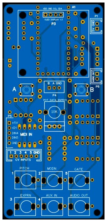
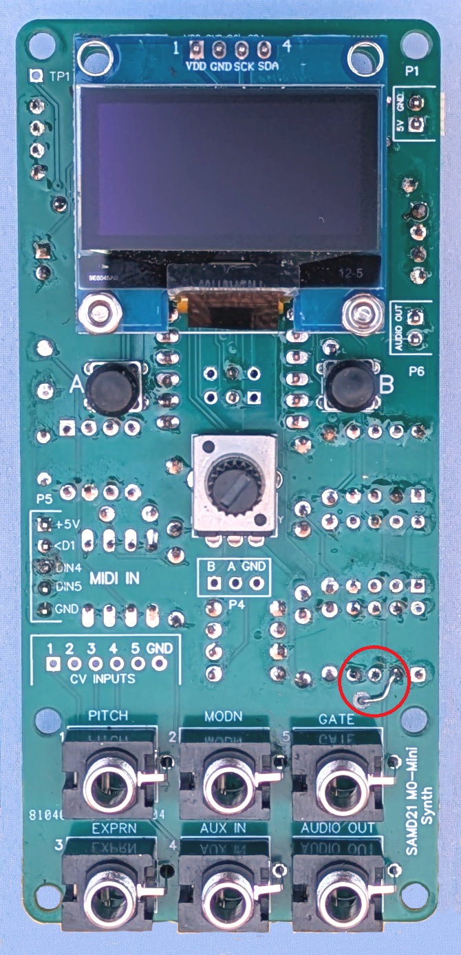
Jack type PJ301M needs a wire link soldered from sleeve lug to GND pad on PCB. Jack type PJ301MB (or compatible type PJ301F) is better suited for PCB mount, but may be harder to obtain. If in doubt, opt for a PCB designed for jack type PJ301M (2A or 2R). This will accept most jack types. This picture shows the board layout (type 2A, v1) and front panel for a Eurorack module.
Gerber files to fabricate PCB based on the Adafruit M0 MCU are ready to download here. Gerber files to fabricate PCB based on the Robodyn M0 MCU are ready to download here. Gerber files to
fabricate PCB for the Eurorack
front panel are ready to download here. NB: It is not cost-effective
to
post boards overseas. It will cost you less to get your own
boards fabricated
in China (including postage). Surplus boards may be offered for
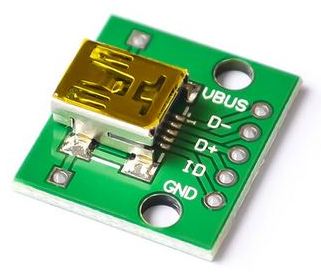
sale in your country... Send email inquiry. Construction notes Be sure to use a polarized pin header and plug for the 5V DC supply (P1). I recommend not to power the module from the MCU USB port, except for firmware updates, for various reasons; e.g. USB "micro-B" sockets are not very robust. For stand-alone Sigma-6 modules, not in a rack, I recommend to use a "mini-B" socket wired to P1 on the PCB for 5V power. USB "mini-B" breakout boards like this are available on AliExpress:
Beware...
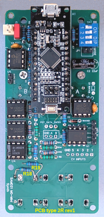
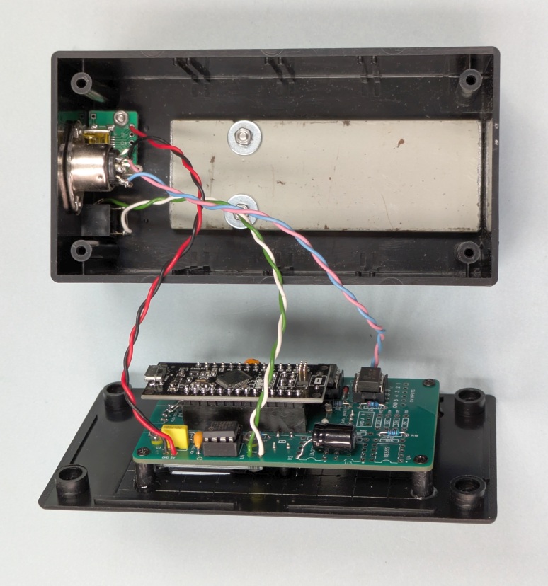
there are variants of the 1.3 inch OLED display available. If your PCB uses the Adafruit 'ItsyBitsy M0 Express' MCU, be sure to fit the extra 2 I/O pins needed on the MCU board (digital '3' and '4' on the short edge) and fit a corresponding 2-way socket strip on the PCB. If your PCB uses the RobotDyn 'SAMD21 M0-Mini' MCU, be sure to fit the extra 2 I/O pins required (MOSI and SCK), i.e. two centre pins (3 & 4) in the 6-pin 'ICSP' connector on the MCU board, and fit a corresponding 2-way socket strip on the PCB. (The other 4 pins in the ICSP connector are not needed.) Synth modules without CV and gate inputs, i.e. using "short" PCB variant, should have R16 fitted in place. The resistor value is not critical... it may be anywhere in the range 2k ~ 100k. Noise from the OLED display controller can appear on the +3.3V supply line which also supplies the audio DAC. This may cause audible noise, i.e. a faint buzz (about 110Hz), on the audio output. The noise should be eliminated by wiring a 100uF (16V) electrolytic capacitor across the OLED supply pins (VDD & GND) on the MCU side of the board. [PCB type 2A & 3A, v1 & v2 only...] There is no provision for R18 or R19 on the PCB. If you intend to use CV control mode, ensure that a 10k and 47k resistor are wired as shown on the schematic. The photos below show PCB type 2R (version 1, modified) with RobotDyn SAMD21 M0-mini MCU fitted.
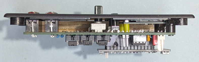
To suit the height of the CV jacks (PJ301M), the space between the PCB top surface and the inside surface of the front panel should be 10mm. The push-buttons and OLED display are mounted accordingly. Assuming a panel thickness of 1.5 ~ 2mm, tact switches (6 x 6 mm) with an 8mm shaft (12mm overall height) will work if they are raised about 1mm off the PCB surface and fitted with 6mm round button caps. The front panel can be held in place with the CV jacks (nuts screwed on) and a couple of plastic spacers (10mm long) at the opposite end of the PCB (top corners). If your synth module is built without CV jacks, the PCB can be held in place with 4 spacers 8mm long. The tact switches can be fitted flush with the PCB surface. There is no need for the extra 1mm height in this case. The OLED display should be mounted on the PCB with four 5mm spacers (2.5mm hole). If your OLED display came with a 4-pin header already fitted, I recommend to remove the pins first, because the header pins may not line up exactly with the PCB pads. Solder 4 wires to the OLED after the display is mounted on the PCB.
Above: Top panel assembly of stand-alone synth module with CV jacks using PCB type 2R Pictured
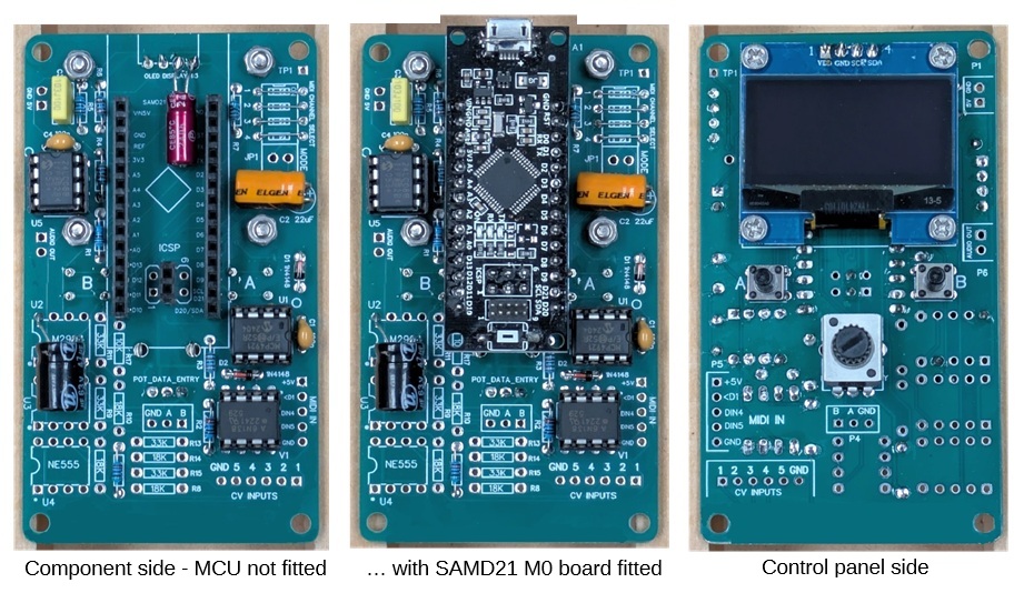
below is the "short form" PCB (v1) without components for CV
inputs. This board is intended for a stand-alone module with
control panel. Note the extra two electrolytic capacitors recommended for supply line filtering:
Hookup wires for 5V IN, audio OUT and MIDI IN may be soldered directly to their respective pads on the PCB. You can use SIL headers and matching plugs if you wish, but this is not necessary. It's unlikely you'll need to disconnect the wires.
Built into a plastic enclosure, the synth module is very light-weight. I recommend to fit a slab of iron in the bottom of the box to add some weight. This gives the module a more solid feel and helps to prevent it from being dragged around on the table top by cables. The slab is 6mm steel, about 35 x 100 mm. Another addition I found worthwhile is a flip-stand on the back of the box allowing the synth to be propped up on an angle (35 to 45 degrees). A flip-stand is easily made with a hinge (35mm) and a piece of plastic (e.g. 3mm perspex) 35 x 65 mm. The hinge is located about 50mm from the top edge of the box in the module pictured here. The same 2 screws that fix the hinge to the back panel also hold the metal slab in place on the inside.
___ Front Panel Decal Panel artwork can be created using Windows Paint, Paint-Shop-Pro, or another image editor. My usual method is to print the decal image on paper, cover it with transparent adhesive film (e.g. bookbinding film), cut holes for knobs, buttons, sockets, etc, then glue it onto the front panel. Sample decal designs are
included in the attached Zip folder... download here.
Decals in the PDF files will print actual size on A4 size
paper. A blank template is also included for you to design your own
panel artwork, in case you don't like the style or colour schemes of
the
samples. Firmware Installation Follow instructions in the 'READ-ME' file on GitHub here: Sigma-6 Synth software repository .. Thanks for
taking
an interest in this project. Feel
free to send comments and queries. for other DIY projects that might be of interest to
you! Last update: 02-MAR-2026 ___ |