|
Build the "REMI Synth" (mk2) A DIY Project by M.J. Bauer |
||
This post describes the design of the "second generation" (mk2) REMI synth module.
|
||
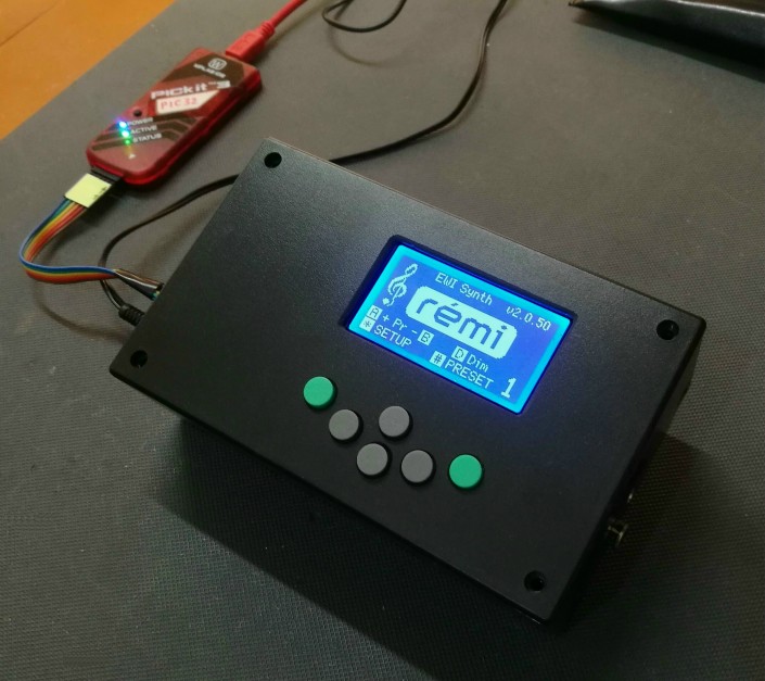
Overview The REMI Synth Module is a monophonic MIDI-controlled sound synthesizer designed primarily for use with electronic wind instument (EWI) MIDI controllers, in particular the REMI mk2 handset. Provision of a standard 'MIDI IN' port allows the synth to be played by any MIDI controller, for example, a keyboard or another EWI with a standard MIDI output. Using a low-cost MIDI-USB adapter, the REMI synth can also be controlled by a computer running music software, for example a MIDI sequencer. Features
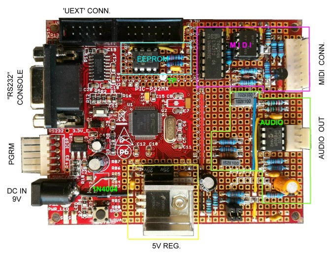
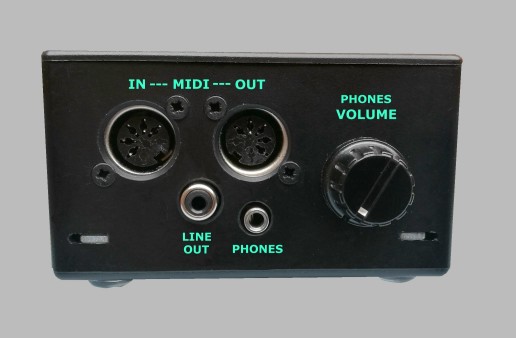 Right-hand side connector panel Synthesizer Design Please refer to the web page describing the revised REMI Synth (mk3).___ Construction Following is a description of the author's prototype construction. There is enough information given here to allow experienced electronics hobbyists to replicate the synth design. Detailed information such as step-by-step instructions, parts lists, etc, are not given in this post. The REMI synth mk2 hardware design is based on a PIC32-MX340 proto board from Olimex (pictured below), priced at €19.95 (US$22 approx). The board has parts added for the MIDI IN and (optional) MIDI OUT interface circuits, plus PWM audio output circuitry, 5V regulator for the MIDI interface and LCD panel, plus an I2C EEPROM (24LC08) to store synth configuration and preset parameters. A separate proto board may be added to carry a headphone amplifier and volume control. View synth schematic diagram The complete module incorporates a front-panel user interface (GUI) consisting of a low-cost monochrome graphic LCD panel and 6 push-buttons. The LCD module and key-switches are wired directly to I/O pads on the Olimex PIC32 board. This is the quickest and easiest wiring method. (See internal view below.) NB: Provision of a front-panel (LCD module and push-buttons) is optional. The REMI synth can be operated completely with the CLI alone. The firmware adapts itself automatically if the front-panel is absent.
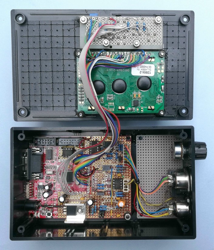
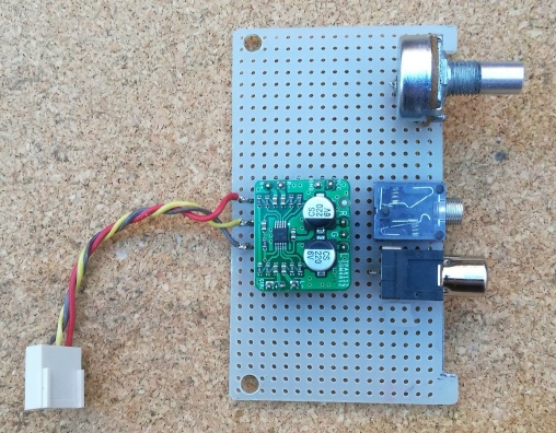
The internal view above shows the LCD panel and push-button board wired to the PIC32 MCU board. Also shown are the MIDI sockets and volume control. A pre-built headphone amplifier (breakout board with TPA6112 IC) was fitted on the prototyping board later, as shown in the photo below.
Boards are mounted on plastic spacers or standoffs. The PIC32 MCU board and audio output board are mounted on the bottom panel of the box using 20mm x M3 machine screws (countersink heads). Standoffs for the LCD module and button board are glued to the inside of the lid (with 5-minute epoxy) so that screw heads are not visible on the outside. 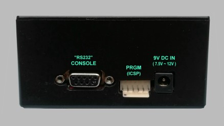 Left side panel showing modified ICSP header protruding thru a cut-out User Guide Details of REMI synth functionality and operation are provided in the Synth User Guide. |
||
If you are interested in building a REMI synth module and/or EWI handset, or if you have enjoyed following the project here, kindly send me an email. Support is offerred to readers who wish to build a REMI or some other electronic music device. [MJB]
Last update: 29-DEC-2021 MJB Resources for Embedded Firmware Development ___ |