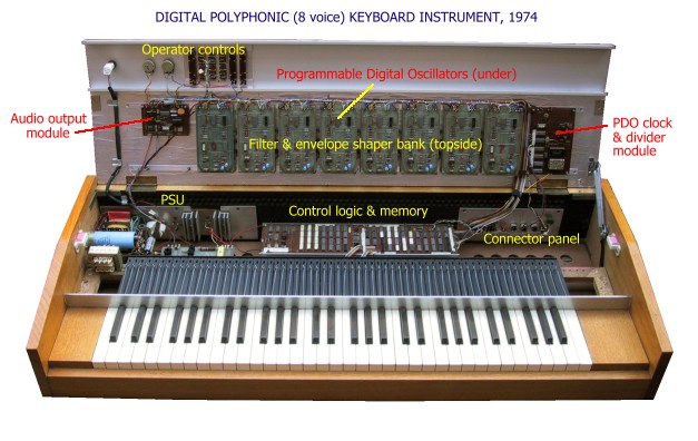
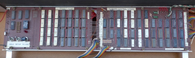
In early 1972, I was part way through building a modular analog synthesizer, a blend of published circuit designs and my own, when I hit on the idea of a digital polyphonic instrument having a bank of eight (or more) identical "voice modules", each capable of generating a tone at any pitch over a range of several octaves. The voice modules would comprise some kind of digital oscillator with programmable frequency, followed by wave-shaping, filtering and keying circuits to provide a variety of instrument sounds. Compared to popular electronic organs of the era, my instrument would eliminate a huge amount of redundancy in the tone-generation and keying circuits. Those old organs had at least one tone generator and keying circuit for each note on the keyboard, resulting in a very complex and cumbersome product. My decision to use digital oscillators, as opposed to analog (voltage-controlled) oscillators, was influenced by the well-known deficiencies of typical VCO circuit designs prevalent at the time; notably the poor stabilty of oscillator frequency and low precision of the exponential transfer function of the control input. Micro-processor devices were not readily available in 1972, so my challenge was to develop a control system using TTL logic devices (9300-series and 7400-series IC's). The function of the control logic would be to scan the keyboard contact matrix to detect key presses and releases. Each active (pressed) key would be assigned to one of the 8 voice modules. The logic would need to set the oscillator pitch according to the assigned note and assert a "gate" signal to control an envelope generator in the respective voice channel. The logic would also need to determine when each active note was terminated (released) and negate the respective "gate" signal accordingly. The prototype logic board (pictured below) used 72 TTL devices.
The keyboard logic could also output binary key-codes corresponing to the notes in progress in each voice/channel. When converted to an analog voltage (using an exponential DAC), the key-code would be able to control sound parameters in the audio post-processing circuitry following the digital oscillator. For example, the key control voltage could be used to make the resonant frequency of a voltage-controlled filter (VCF) track the pitch of the oscillator. A
hybrid polyphonic instrument incorporating the best advantages of both
the digital and analog worlds was realised. No doubt, there would have
been commercial companies attempting to develop a polyphonic keyboard
synthesizer at around the same time. Of course, their ideas were
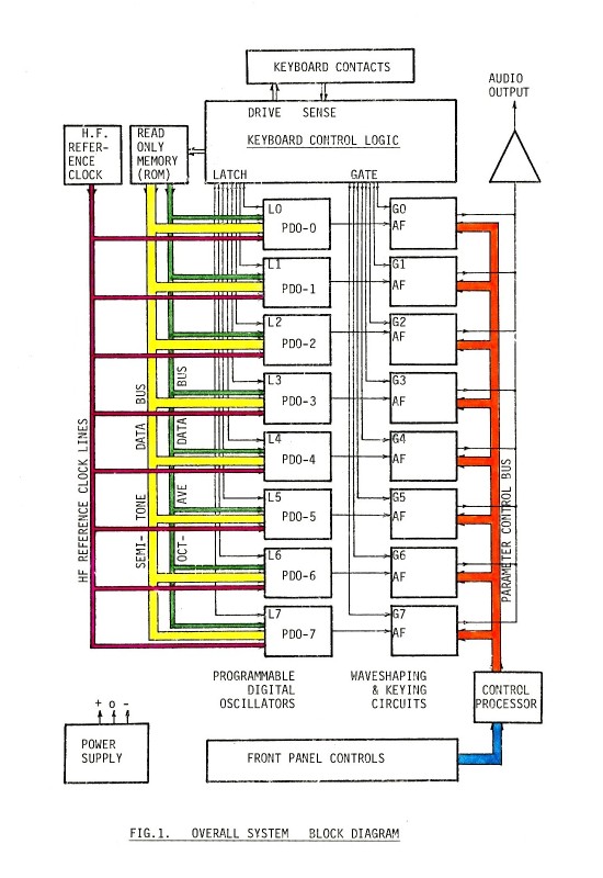
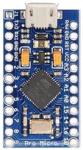
kept a closely guarded secret. Unfortunately, my instrument was not destined to be a commercial success. Apart from my lack of entrepreneurial skills, there were other factors leading to its swift obsolescence. The keyboard logic was implemented entirely from small-medium scale TTL devices. It was based on a kind of state-machine architecture. A little invention called the "micro-processor" made my TTL design obsolete. My "prototype" instrument did not incorporate a controlled resonant filter in the voice modules. The post-oscillator audio processing circuits were rather primitive. Having achieved "proof of concept" in the keyboard control logic and programmable digital oscillator designs, I moved on to other projects. In 1976, two years after I completed my "digital polyphonic keyboard" project, Motorola introduced the M6800 'D1' evaluation kit. I acquired one of these, and so began my career in embedded electronics. The Restoration More than 50 years later, I got the old keyboard out of storage in the attic. It seemed a shame to throw it in the trash. I am hopeful that a collector and enthusiast of vintage electronic music equipment will want to take possession of it and continue with its preservation. Of course, nobody would want it unless it was in fully operational condition. When I powered it up for the first time in over 30 years, it failed to function... not surprisingly, given its age. Preliminary testing revealed a fault in the 5V (5A) logic power supply. It had an over-voltage protection circuit called a "crowbar". If the PSU output voltage exceeds a preset threshold, 5.5V, a controlled switch (SCR) short-circuits the output. This is meant to blow a fuse at the input to the voltage regulator. An over-voltage event must have occurred, but apparently the fuse failed to blow, resulting in the destruction of two hefty 30A rectifier diodes (SPD9002)! Repairing or replacing the power supply won't be difficult. Likewise, it should not be too difficult to fix a fault in a voice module (PDO or envelope shaper). But what if there's a fault in the control logic assembly? The original schematics and documentation are very sketchy and were not maintained exactly "as-built". Schematics in the published articles (1976) are revised, simplified versions of the originals, based on hindsight, and never tested. Even if the original schematics were accurate, it would be very challenging for me or indeed anyone else to diagnose and fix a fault. Hence, to avoid the scenario of anyone having to fix a fault in the control logic, I made the decision to bypass it with a microcontroller-based functional equivalent. The original logic board will remain in place, disconnected, to preserve the original character of the instrument. A discretly hidden MCU-based replacement will connect to the keyboard contacts (already wired in an 8 x 8 matrix). The MCU board will interface to the bank of programmable digital oscillators (PDOs) via the existing ROM board, and it will output "gate" signals to the 8 envelope generators. Below is a block diagram of the instrument. The "keyboard control logic" block is to be replaced with a micro-controller board. The ROM converts a key-code (note number) into semitone data which feeds into a bus. The semitone and octave data are latched into one of the PDO's whenever a note is initiated.
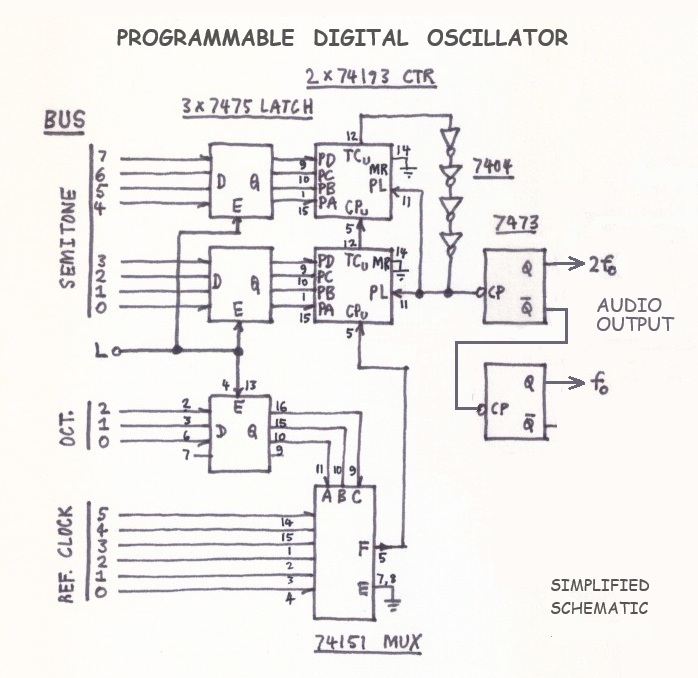
Following is a (simplified) schematic of the Programmable Digital Oscillator. The complete PDO board included some primitive digital wave-shaping circuitry which generated audio pulse signals of various frequencies (relative to the fundamental) which could be combined to produce a variety of sound timbres.
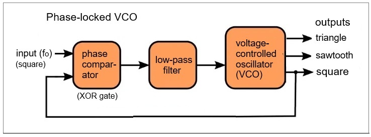
To generate a tone at the desired frequency, first the keyboard control logic must latch the required semitone and octave data into the three 4-bit latches (7475). The 3 octave bits simply select one of 6 "reference clock" signals via the multiplexer (74151). The clock lines are sourced from a binary counter on the "master clock" board so that each clock line is exactly half the frequency of the next higher line. The heart of the oscillator is an 8-bit parallel-load binary counter (2 x 74193) which counts up from the programmed data input (latch outputs) until it reaches the "terminal count" (binary 1111 1111). The TC output is fed back into the "parallel load" input (PL) via a delay line (4 inverters). The delay ensures a minimum pulse width (around 40ns) to re-load the counters reliably. Thus, the number of clock pulses in a counter cycle can be varied over the range 1 to 256 clocks. In reality, bit 7 of the semitone data is always low, so that the usable count range is 128 to 256 clocks, i.e. one octave, yielding a best case resolution around 1/256th of an octave for the period of the output audio signal. Perhaps surprisingly, the worst-case error in pitch is only about 3 cents (0.03 of a semitone) which, for all but the most demanding musical purposes, is acceptable. Pitch accuracy could have been improved by extending the number of bits in the semitone data bus and raising the frequency of the master clock. In hindsight, it would have been possible to devise an audio wave-shaping scheme that produced more musically-useful waveforms, e.g. sawtooth, triangle and variable-duty pulse, directly from the square-wave output of the PDO. A phase-locked loop incorporating a VCO could serve this purpose.
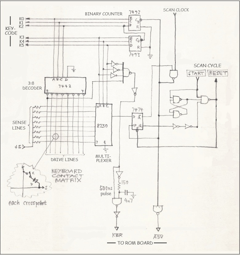
However, I do not want to make any modification to the PDO or wave-shaping circuits. The plan is to preserve the original character of the instrument; only to replace the keyboard logic with a micro-controller. Key contact scan logic The 64 keyboard contacts are wired into a matrix of 8 x 8 crosspoints. The original scan logic used a 3:8 line decoder with active-low outputs to drive the 8 columns in the matrix, and an 8-input multiplexer to sense key closures on the 8 rows. The 8 "drive lines" were activated (low) one at a time in sequence while the other 7 lines remained in the high state. The "sense lines" were held in the high state by pull-up resistors. A single key closure would result in a sense line being pulled low by the active drive line. To scan a keyboard in polyphonic mode requires multiple simultaneous key closures to be recognized. That's where things get a little complicated. I discovered (the hard way) that wiring the key contacts in a 2D matrix gives rise to a problem that I call the "phantom key effect". Fortunately, I came up with a simple solution which was to put a diode in series with every contact, as shown here in the original 1972 schematic:
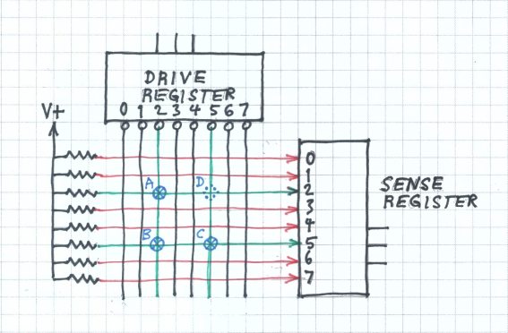
The "Phantom Key Effect" Consider the diagram below, assuming there are no diodes. Key contacts at three crosspoints, A, B and C, are closed. When the drive line D2 is activated (low), sense lines S2 and S5 will be pulled low. The sense register will correctly identify that keys A and B are pressed. But when drive line D5 is activated (low), sense line S2 will again be pulled low, indicating wrongly that key D is also pressed. The false reading occurs because key C pulls sense line S5 low, key B (on the same sense line) pulls drive line D2 low, and so key A pulls sense line S2 low. The diodes prevent all sense lines from being able to pull any drive line low, thereby eliminating the problem.
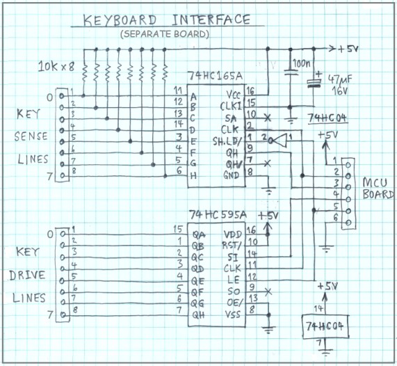
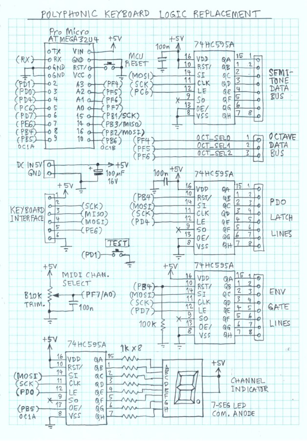
The diodes also prevent the active drive line being short-circuited to another drive line when multiple keys are pressed, which could potentially damage the decoder chip. In standard TTL devices, if two outputs are shorted together, one in the high state and the other in the low state, the low state will dominate, because the low-state output current sink capability greatly exceeds the high-state current source capabillity. Alternative ways to scan a keyboard There are other methods to scan a keyboard which avoid the "phantom key" problem. Not only that but the contacts may have a common pole, i.e. when a key is pressed, its contact closes onto a wire rail spanning the entire keyboard. This sort of contact cannot be wired into a 2D matrix. For example... (1) Use a 64-input multiplexer, which would be implemented typically using four 16-input multiplexers. If the contacts are simple SPST types, then a pull-up resistor would be required on all 64 inputs. To interface the MUX to a micro-controller requires 8 I/O pins: 4-bit address (output) plus 4-bit data (input to the MCU). (2) Use a 64-bit parallel-in serial-out (PISO) shift-register. My recommended implementation would be to use eight 8-bit PISO registers, e.g. 74HC165A, wired in series. As in case (1), a pull-up resistor may be required on all 64 inputs. An advantage of this method is that the register can be interfaced to a micro-controller via a synchronous serial port (SPI bus), requiring only 3 I/O pins (SCK, MISO, SH/LD). Keyboard Interface for the Replacement Logic Since the key contacts are already wired in a 2D 8 x 8 matrix, with "anti-phantom" diodes, it seemed like a wise decision to leave it that way. It's simple enough to connect the contact matrix to a micro-controller via a pair of shift-registers, one serial-in parallel-out (74HC595A) and the other a parallel-in serial-out register (75HC165A), both of which can be interfaced to the MCU via an SPI port. These components can be mounted on a separate "sub-board" to be located near the keyboard. The sub-board needs only 6 wires to be routed to the main MCU board, including VCC and GND. Here's the schematic:
The micro-controller can read the sense lines and write the drive lines (for the next reading) in the same 8-bit SPI data transfer. Annoyingly, the PISO register SHIFT/LOAD signal (pin1) has opposite polarity to the SIPO register's latch enable (LE) signal, requiring an inverter on the SPI "slave select" line. I could have used two separate MCU I/O pins for this purpose, but I think the inverter results in a more elegant solution. Control Logic Replacement
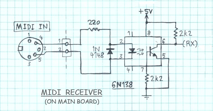
Test and Setup Mode A highly desirable feature to include is some kind of user-interface to allow setup and testing of the voice modules (PDO and envelope shapers) individually, i.e. one at a time, in monophonic mode. This was realised by one push-button (TEST) and a single 7-segment LED digit driven by a SIPO register. The idea is that the firmware will enter a monophonic "setup mode" if the TEST button is held pressed for longer than (say) three seconds. The voice/channel to be tested/calibrated is indicated on the 7-segment LED. A momentary press of the TEST button will advance to the next voice/channel to be tested. In normal operational mode, the 7-segment LED digit indicates the MIDI channel number (1 to 9) which is selected by a trim-pot feeding into an ADC input (A0). If channel 0 is selected, then MIDI "Omni On" mode is activated, i.e. the instrument will respond to messages addressed to any MIDI channel. MIDI Support The above schematic doesn't show a MIDI IN receiver circuit. It would not fit all on one page, so I drew the MIDI IN circuit on another page (see below). Provision of MIDI control was an after-thought, but so simple to add that I could not possibly leave it out.
___ Power Supply Upgrade Progress
on the restoration has been slow. The main reason is I am too
easily distracted by a new project I'm working on. Also, the old
keyboard poses numerous challenges as outlined earlier. First, I had to
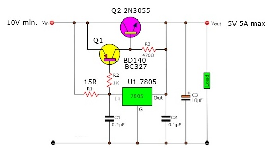
repair the 5V power supply. The original power supply failed, not
surprisingly considering the total load current into the TTL logic was
around 5 amps!! The rectifier diodes were rated at 10A continuous, but they burnt out regardless... probably due to aging.
After testing this power supply with a dummy load, I connected it to the bank of 8 digital oscillators. The current draw was 2.8 amps. That's 350mA for each oscillator! This seemed way too high, so I looked up the datasheets of some of the TTL devices used. I had forgotten how power hungry these old ICs are. The 74193 4-bit counter draws typically 65mA. So the total 350mA per board doesn't seem abnormal after all. The
next step is to test the digital oscillators to see if they still
function properly. For this, I need to build at least part of the
MCU-based "logic replacement circuit". ... ... to be continued ... For historical interest, the original design of the Digital Polyphonic Keyboard is posted here... Electronics Australia magazine article (April, 1976): [Page1] - [Page2] - [Page3] ___ <!> Attention: collectors of vintage electronic music apparatus... I
would be grateful to hear from anyone, preferably resident in
Australia, who may be keen to take possession of the prototype
instrument with a view to preserving it for posterity.
Page last updated: August 2025 |

![[Page1]](Keybd_EA_article_p1.GIF)
![[Page2]](Keybd_EA_article_p2.GIF)
![[Page3]](Keybd_EA_article_p3.GIF)