| ___ "Sigma-6" Polyphonic Synthesizer ___ DIY project blog by M. J. Bauer ___ |
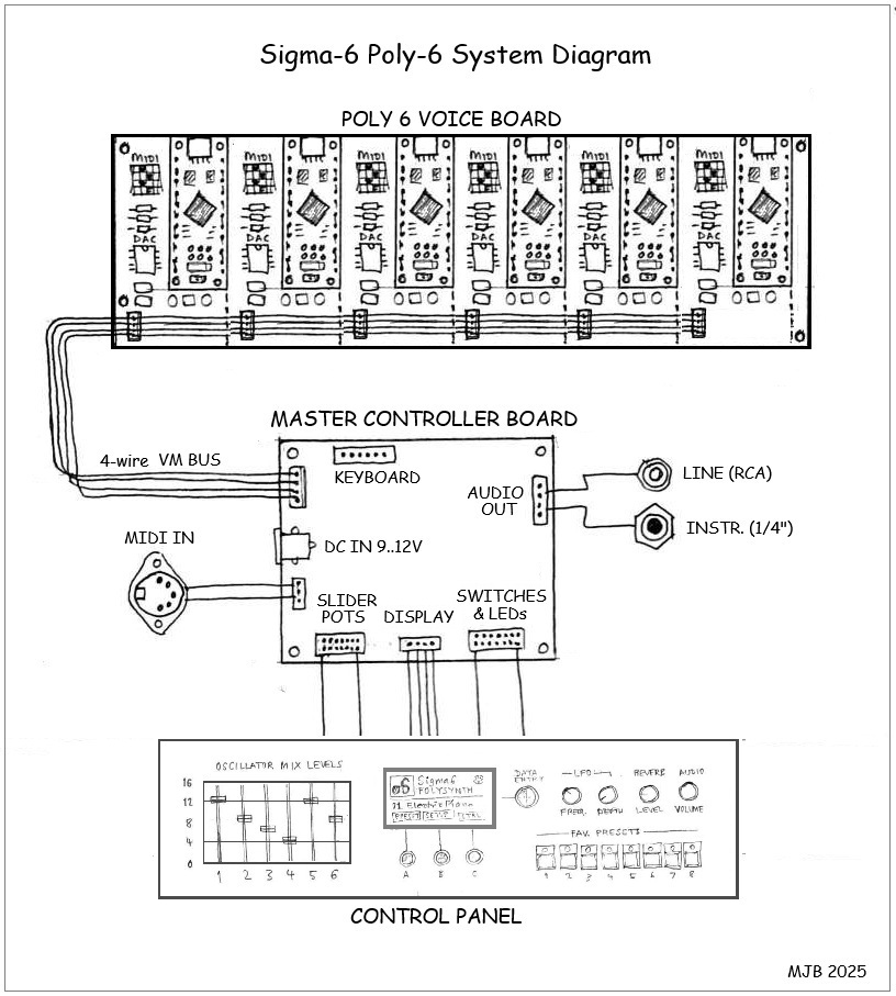
Following the success of the monophonic 'ItsyBitsy M0 Sigma-6' synth, it seemed inevitable that a polyphonic version would be developed. A Poly Sigma-6 box may be built for connection to an external MIDI controller-keyboard, or the synth parts could be incorporated into a keyboard enclosure. Each voice in a Poly Sigma-6 synth comprises 6 oscillators, mixer, 3 envelope shapers, LFO with ramp, variable-gain attenuator (DCA), plus overdrive and reverberation effects. The firmware includes a diverse range of instrument sounds (factory presets). More presets will be added in future revisions. A unique feature of the Sigma-6 tone-generation scheme is its ability to modulate the signal amplitudes of the six oscillators independently by a selection of modulation signal sources. Contrary to the conventional "DCO-DCF-DCA" model, the Sigma-6 uses an innovative synthesis technique capable of producing some refreshingly different and appealing sounds. Click here for details... View/Download doc explaining the Sigma-6 synthesis method System Overview The Sigma-6 Poly-synth comprises up to 12 "voice modules"
connected via a MIDI bus to a "Master Controller" board, the
function of which is to interpret MIDI messages from a polyphonic
controller (keyboard or sequencer) and allocate keyed notes to the voice
modules. The Master Controller has a front-panel user
interface, so the individual voice modules do not need a control
panel.
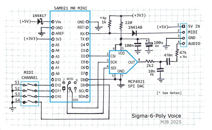
The Robotdyn 'SAMD21 M0-Mini' MCU board costs about $5 on AliExpress. The SPI DAC (MCP4921) costs under $2 (SOIC-8 pkg), so the parts cost for the voice modules is minimal. A complete Sigma-6 Poly-synth will be very inexpensive to build. Here's an outline diagram showing a poly-synth system with 6 voices:
Sample Sound Clips
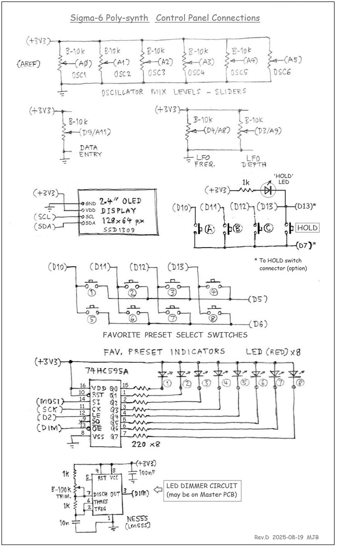
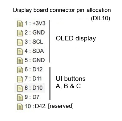
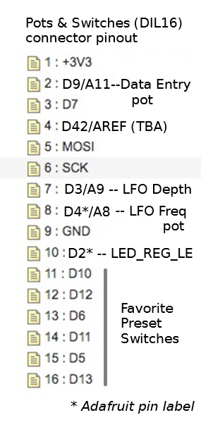
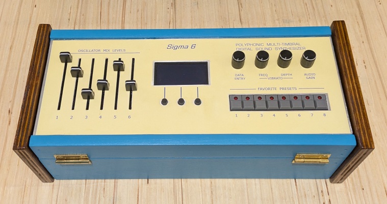
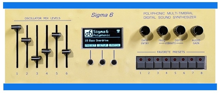
'Walkyrie' - Clip made using a Jazz Organ preset (Courtesy of Jean-Pierre Meyer) 'Pink Panther Theme' - Clip made using two different organ presets (Courtesy of JPM) 'Mussorgsky Sonata' - Piece in 4 parts using 'Trashy Toy Piano' preset (JPM) 'Rhapsody in Blue Toy Piano' - with apologies to George Gershwin - (Clip by JPM) 'Danse Slave' - Extract from a piece composed by Dvorak - (JPM) 'Pink Panther take-2' - Stereo & multi-timbral recording - (JPM encore) 'Pink Panther take-3' - Imitation Rhodes electric piano - (JPM encore) Demo video coming soon. User Interface - Control Panel The control panel of the polyphonic synth can have (optionally) a bank of 6 slider pots (or rotary pots) allowing the user to set the output levels of the six oscillators, i.e. to change the mixer input levels defined in the selected preset. When a slider is moved, the respective oscillator mixer input level will be set according to the slider position, over-riding the level defined in the preset last selected. The sliders provide similar functionality to the "draw-bar" controls in Hammond organs. To facilitate fast change of preset during a live performance, a row of 8 push-button switches will allow selection of a "Favorite Preset". The 8 "favorites" are user-configurable from a greater number of instrument presets stored in flash memory. The switches have an LED to indicate the selected preset. A graphic OLED display, with 3 buttons and a 'Data Entry' pot, provide various other user-interface functions, e.g. to set up configuration parameters, to select a preset (other than favorite) and to adjust active patch parameters. The firmware also provides 8 'User Presets', i.e. the ability to save and load the active patch as a user-defined preset (aka "Favorite") stored in EEPROM.
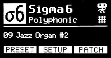
Front-panel User Interface - 'Home' Screen Various icons will appear on the "Home" screen (pictured) to indicate instrument status, e.g. MIDI input activity, patch modified, etc. The little robot icon is a legacy from the monophonic "ItsyBitsy M0" synth, indicating the type of MCU fitted. (Although now redundant, it seemed a pity to delete it.) User Guide When firmware is installed for the first time, the 8 User Presets will be defaulted (initialized) to "factory" (voice) presets 1 ~ 8 (copied from a table in flash memory), all named 'Unnamed_Fav_Preset' pending new names to be assigned. All configuration parameters are defaulted to predefined values. The
default names assigned to User Presets are not the same as the
derivative "factory" defaults because it is assumed the User Presets
will be modified at some time or other. New names can be assigned via the command-line user interface. When you enter the 'PRESET' screen, it will display the last factory preset selected, regardless of the preset displayed in the Home screen (which may be either a user preset or a factory preset). A User Preset is recalled by pressing one of the 8 Favorite preset buttons. The recalled preset then becomes the 'active patch'. To copy a "factory" preset into a User Preset (Favorite) and keep the original instrument name:
The User Preset will be an exact copy of the Factory Preset, including the name. Parameter setting modes Reverb Level:
Moving the Data Entry pot (in the Reverb screen) will adjust the
setting. The change takes effect immediately; i.e. the new setting
is sent to the voice modules. The Reverb setting is saved in EEPROM
only if the [Affirm] button is pressed; otherwise the setting is
temporary. Oscillator Mix Levels: Moving a Slider pot (1 ~ 6) will adjust the respective setting and the change will take effect immediately; i.e. the new setting will be sent to the voice modules and the new setting will be written to the "active patch" parameter. The change will be persistent, until a new Preset or Favorite is selected. All other patch parameters: Moving the Data Entry pot will adjust the setting displayed, but the new setting will not take effect until the [Affirm] button is pressed. When Affirmed, the setting will be transmitted to the voice modules and it will be written to the respective "active patch" parameter. Note: Some parameter changes may not take effect while a note is playing. These changes will take effect when a new note is initiated. Pitch-Bend and Vibrato are mutually exclusive. You can enable either Pitch-Bend or Vibrato (LFO FM), but not both at the same time. A planned firmware revision will allow both effects to function concurrently. Tuning Procedure The Poly Sigma-6 has provision to tune the voice modules individually. The voice MCU's have a precise crystal oscillator for the system clock, so it should not be necessary to tune the voice modules differently. The default tuning parameters (0) should produce "concert pitch", i.e. A4 = 440.00Hz. If you find one or more voices slightly "out of tune", use the 'Voice Tuning' facility from the SETUP menu to ensure that each voice is in "concert pitch". But first, set the 'Master Tune' parameter to zero (default) if it is not already zero. Assuming the voice modules are all set to concert pitch, you can then use the 'Master Tune' facility
to adjust the pitch of all voices together by the same amount. This may
be convenient if you need to tune the synth to the same pitch as an
acoustic instrument, instead of vice-versa. Hold/Sustain Operation * The Poly Sigma-6 supports a "Hold/Sustain" function whereby the amplitude envelope (ENV1) can be held in the Sustain state, i.e. it will not enter the Release state when a MIDI Note-Off message is received. Any note(s) held in Sustain will be released when the Hold/Sustain mode is canceled. The
Hold/Sustain mode can be controlled in either of two ways: (1) by a
push-button or foot-switch connected to the Master controller, or (2)
by a Control Change message (CC64) sent by the attached MIDI
controller. If option (1) is selected -
button or foot-switch - the switch action is a toggle... push-ON
/push-OFF. Option (2) - MIDI controller operation - conforms to the
MIDI Specification for Hold operation. Multi-timbral Operation (mix of Poly + Mono voices) * The Poly Sigma-6 synth can be configured so that a number of voices function together as a polyphonic group while other voices function as independent monophonic voices with arbitrary preset sounds. This is termed "Multi-timbral" or "Mono/Poly" mode and this requires a MIDI keyboard (or keyboards), or sequencer, capable of sending MIDI messages to more than one voice channel. All respectable DAWs have this capability. * Requires Master Controller firmware v1.20+ with Poly-voice firmware v1.8+ A SETUP screen titled "Voice Config" allows you to specify the number of voices which operate in the polyphonic group. Voice channel numbers must begin at 1 and must be consecutive, including voices that could function in monophonic mode. Channel numbers assigned to Mono voices are above the Polyphonic group. The 'Number of Poly Voices' is a persistent parameter stored in the master EEPROM. Voice channels above this number are assumed to be assigned to Mono mode. For the synth to operate in 'Multi-timbral mode', the 'Number of Poly Voices' must be less than the total number of voices in the system. The total number of physical voices is specified in the Master program code. A #define directive is provided for this purpose. Simply assign the appropriate value to the symbol 'MAX_NUMBER_OF_VOICES' before compiling and uploading the firmware. Voice modules with MIDI channel (DIP-switch setting) higher than the 'Number of Poly Voices' operate independent of the Poly-voices. The MIDI controller keyboard(s) or sequencer must address MIDI messages directly to the Mono-voice channels to respond, as if they were separate synth modules each with a unique MIDI address, which they are, in effect. However, the group of Poly-voices will respond only to messages addressed to the MIDI basic channel (Master controller), as if it were a separate Poly-synth. Example: A Poly Sigma-6 with 8 physical voices can be configured for 6-voice polyphony, with two extra voices available for independent monophonic operation. The Mono-voices may be set up with preset sounds appropriate for lead and bass parts, respectively, while the Poly-voice group is set to a preset appropriate for accompaniment with chords. In this example, the MIDI basic (master) channel may be set to any channel (1..15) except a Mono-voice channel. The two Mono voices will be assigned to channels 7 and 8. Mono-voice presets may be selected via the user interface's SETUP menu: "Voice Config" option. After confirming the 'Number of Poly Voices', press [Next] to enter the "Mono Presets" function. The Master saves the selected Mono voice preset(s) so that on restart, the last saved preset(s) will be restored. In addition, a preset may be assigned to any voice by the MIDI controller (keyboard or whatever) sending a MIDI "Program Change" message addressed to the voice channel, with the Preset number. Program Change messages addressed to the Master (basic) channel will be forwarded to all Poly-voices together. Patch parameters of Mono voices are not adjustable via the Master user-interface (control panel). Some parameters are settable via MIDI CC messages. (Refer to the "MIDI Implementation" section of the Sigma-6 voice module web page. Mono voices will respond to CC numbers 70 thru 79, plus 87, 88 and 89.) Note that some MIDI "song" files available for downloading from various websites may have MIDI Program Changes embedded. The "program" numbers usually conform to the "General MIDI" (GM) standard so that the selected instrument sounds are appropriate for the "song". The Sigma-6 synths do not comply with the GM standard! The preset numbering scheme is quite arbitrary. Hence, you might need to change the Program numbers embedded in your MIDI song files to get the music to sound right. Popular DAWs (e.g. Ableton Live) provide an "automation track" in which MIDI commands can be embedded. You can edit this track to insert Program Change commands appropriate for the Sigma-6 sounds. _____________________________________ Command-Line User Interface (CLI) The
firmware also implements a simple CLI, accessed via the USB port using
the Arduino 'Serial Monitor' tool, or a PC 'Terminal' program (e.g.
"PuTTY"). The Terminal app Baud-rate should be set to 57600, but
it may not matter for USB-serial. > save fav# [name_string] <Enter> ...
where 'fav#' is the number of the Favorite to be saved (1 ~ 8) and
'name_string' is a name to be assigned to the Favorite/Preset.
[Don't type the square brackets -
they indicate optional param.] _____________________________________ Presets 32 ~ 63 ... Explanation of Nomenclature The names given to "factory" presets 32 thru 63 are based on patch parameters which are not settable via the front panel user-interface or controls. The first word in each preset name is a colour. The colour indicates the combination of frequency multipliers assigned to the six oscillators, as shown in this table:
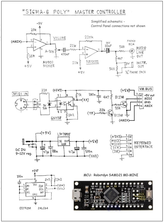
Values shown are frequencies relative to the fundamantal frequency of the note. These numbers also represent the harmonic order. For example, a value of 3 represents the 3rd-order harmonic. Of course there are many other possible combinations of harmonics and sub-harmonics. You can experiment with various combinations by modifying existing presets or by adding your own presets in the program code. The amplitude of each oscillator, i.e. the mixer input level, is settable via the front-panel sliders. The sound characteristic (timbre) of a preset may be varied dramatically by changing the relative oscillator levels. Following the colour in each preset name is a string indicating the source of modulation of one or more oscillators. If there is no modulation applied, the text "No Osc AM" appears. The abbreviation "Modn" means that one or more oscillators can be modulated by MIDI Modulation messages (Control Change 01). Other preset provisions are modulation by the Contour envelope generator or by the "Transient" generator (ENV2/EG2). Any oscillator(s) affected by a modulation source are shown in the preset name. Lastly, the word "detune" may appear, indicating that some oscillators in the group are detuned relative to others. As noted earlier, preset/patch parameters associated with the low-frequency oscillator (LFO), Amplitude Envelope (ENV1) and Overdrive (Mixer Gain and Limiter Level) are settable via the user interface, so you can experiment ad lib with these settings. When you are satisfied with a new sound you have created, you can save it as a Favorite preset and/or make it permanent by writing it into the program code. Electronics Design Here is a schematic of the Master Controller board. This doesn't show connections to the front-panel controls and indicators, OLED display, etc. These connections are shown in the next schematic.
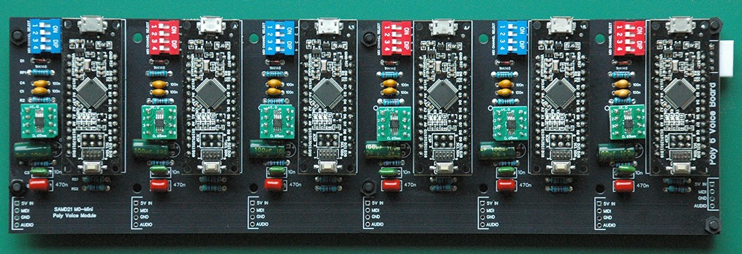
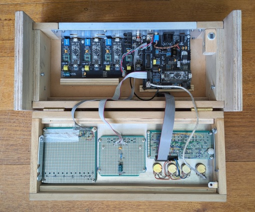
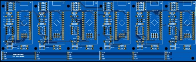
Construction The Sigma-6 Poly-synth comprises two or three main circuit boards, i.e. a 'Master Controller' and 1 or 2 'Poly-6 Voice' boards (pictured below) plus control panel parts (OLED display, pots and push-buttons) which may be mounted on prototyping matrix board (aka "perf-board") or custom PCBs. Rotary pots may be mounted directly on the front panel if preferred.
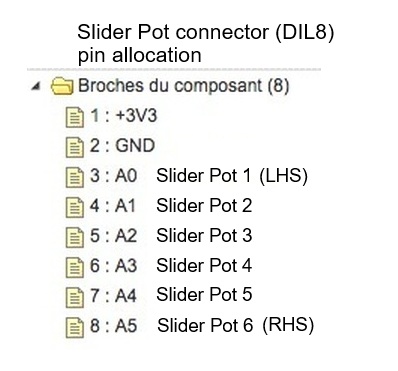
The charts below give the pinouts of connectors on the Master board (v1.5) for wiring to the front panel boards and other panel-mounted parts.
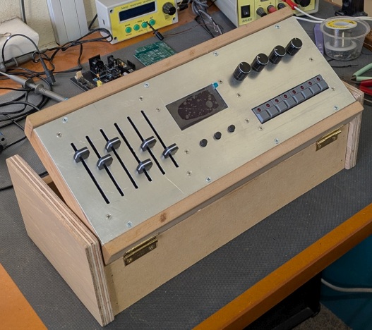
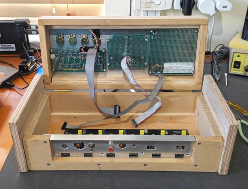
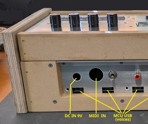
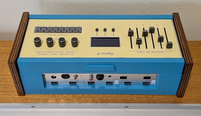
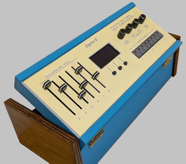
Assembly Notes Do not fit the 6 resistors marked Rs2 (47k) on the Poly-6 Voice board (early revisions of the PCB). On the Master board, PCB-mount connectors for DC power and MIDI IN are optional. Connectors are provided for alternative off-board panel-mount parts if preferred. There is also a connector for an optional DC power switch (panel mount). If a switch is not fitted, place a link on the header. A suitable heat-sink should be fitted on the 5V regulator IC (LM7805). Total load current is not expected to exceed 400mA with 12 voices powered. (Maximum power dissipation: 1.6W with 9V DC input.) If you are making your own custom board for the Favorite Preset switches and associated circuitry (LED register), I recommend to provide a DIL20 pin header to connect to the Master board via a 20-way IDC ribbon cable. The custom board should provide pin headers for wiring to panel-mounted pots (Data Entry, LFO Freq, LFO Depth). The Volume Pot should be connected directly to the Master controller board via the SIL3 header. I recommend to use screened cable with the screen wired to pin3 of the pot. It is not necessary to fit socket strips on the Poly-6 Voice board for the SAMD21 MCU module. The required MCU pads may be soldered directly to the voice PCB using bare tinned copper wire (24~28 AWG). You only need to solder I/O pads which are essential in the circuit, of course. The MCU module can be held in place with double-sided adhesive foam tape (1.5 ~ 3mm thickness) of the sort used to mount a painting or mirror on a wall. The foam tape also serves to insulate the MCU from the mother board. The SPI DAC chips (MCP4921) are cheaper to buy in the SOIC package style than the DIP-8 style. You can buy little break-out/adapter boards to allow SMD's to be fitted to a DIP PCB footprint. The Poly-6 Voice PCB assembly pictured above uses MSOP devices which are even smaller than SOIC. I advise not to use MSOP devices unless you have good SMD soldering skill. Be sure to set the MIDI channels of the voice modules in sequence, beginning with channel 1. There must not be any gaps in the sequence. If one or more of your voice modules is not functioning properly and you want to exclude them from operation, set their MIDI channels higher than the number of voices specified in the firmware code. The channel numbers do not need to follow the physical order of voices on the board. Enclosure (suggestions) I chose to build my prototype Poly Sigma-6 into a custom-designed wooden box with an aluminium top-front panel. The control panel parts are mounted in a hinged top section allowing easy access to circuit boards for service and modification (if necessary). For convenience in operation of controls, the hinged top section can be propped up at an angle, i.e. 30 or 45 degrees. The lower section of the box contains one Poly-6 voice board and the Master controller board. There is enough spare room beside the Master board, above the Poly-6 board, for two single voice modules to make a total of 8 voices. A bigger box would be needed to house two Poly-6 voice boards. I'm not giving dimensions of the enclosure or detailed build instructions because my control panel was made using prototyping board instead of the PCB's designed by Jean-Pierre (see below). Construction will be much easier using the custom panel PCB's, but of course the enclosure dimensions will be different. If you decide to build an enclosure of similar design, I recommend to allow a liitle more space above the Poly-6 voice board to place the Master board... at least 25mm between boards. In my proto box, the Poly-6 Voice PCB is mounted on 4 plastic standoffs fixed to the bottom of the box. The Master PCB is supported at the back by 2 small metal brackets fastened to the back panel and at the front by stand-offs placed on a piece of plywood glued to the bottom of the box. I'll use the same method to mount the extra 2 mono voice modules later. Whatever enclosure design you choose, be sure it allows easy access to the USB sockets on the micro-controller modules for firmware updates, and for connection of a CLI "terminal" to the Master MCU.
I had some blue paint left over from another project. It makes a nice change from matte black, I think, and contrasts nicely with the (walnut stain) varnish on the end pieces. The front panel decal was designed using MS Paint, laser-printed on stiff paper (AU$1.80 at OfficeWorks) then glued to the aluminium panel. I would have preferred to etch labels directly onto the aluminium, but this requires processes and skills which I don't have. Also, the aluminium had some scratches on it. Printed Circuit Boards Project collaborator and DIY synth enthusiast Jean-Pierre (in France) has already designed the PCBs.
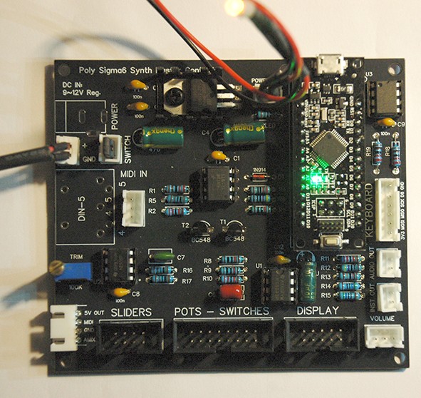
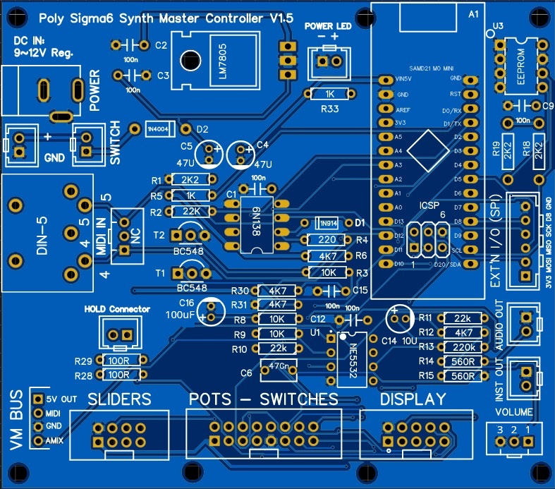
Using 2 of these boards, you can build a poly-synth with up to 12 voices. There is also a PCB design for a single voice module, in case this may be more convenient to extend a synth to 8 voices. And here's a pic of the essential "Master Controller" board...
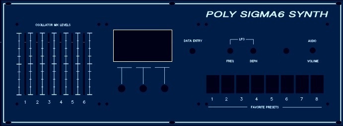
Jean-Pierre has also designed boards for the control panel...
(NB: The PCB's pictured here may not be the latest revisions.) Latest revisions of Gerber files to fabricate the PCB's are available on request. Surplus boards (bare PCB - not assembled) may be available for purchase. Send email inquiry for details of PCB availability, prices, postage, etc. Firmware Sigma-6 synth software is compiled using the Arduino IDE, so if you have C programming skills, you can modify and extend the (open-source) programs to suit your own requirements. To install firmware, follow instructions in the 'READ-ME' file on GitHub, here... Sigma-6 Poly-synth software repository ___ Thanks for taking an interest in this project. Feel
free to send comments and queries. for other DIY projects that might be of interest to you! |