|
DIY MIDI Controller Keyboard Project blog by M.J. Bauer |
|
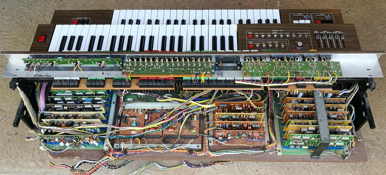
There must be lots of faulty or obsolete keyboard instruments out there which could be given a new life as a MIDI controller for synthesizers. This blog reports on how I went about it... A while back, I found an old electronic organ made by ELKA that someone had thrown in the trash. The instrument had been left out in the weather and many parts were damaged beyond repair. Luckily, the two keyboards (each with 44 keys) were in good condition physically. The contacts were badly tarnished, but they can be cleaned using a solvent or mild abrasive. Since there was no hope to restore the organ, I decided to build a MIDI controller around one of the keyboards.
Photo: Upper section of old Elka organ which contained most, but not all of the electronics The MIDI controller will use a Sparkfun 'Pro Micro' MCU
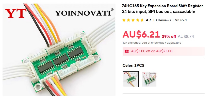
module (ATmega32U4, 8-bit AVR, 5V/16MHz). The USB port can be used for firmware update (DFU) and to provide a simple command-line user-interface (CLI) intended mainly for debug usage. DC power supply options will be 9V..12V via a 5.5mm barrel jack, or 5V via the USB port, or 5V via "Power-over-MIDI" (from the MIDI OUT socket). This will allow the keyboard to be powered by a Sigma-6 Poly synth through the MIDI cable. This MIDI controller design is intended for keyboards without velocity-sense capability. Many older keyboard instruments, e.g. electronic organs, have a key contact mechanism unsuitable for velocity measurement. Hence, provision will be made to generate a "fake" velocity signal using a front-panel control knob or a plug-in foot-pedal. The simulated velocity signal will be transmitted in MIDI Note-On messages, of course. The keyboard contacts will connect to the MCU via a couple of input port expansion boards, each accepting up to 24 key contacts wired to parallel inputs of shift-registers, type 74HC165. Each input pin has a pull-up resistor, so the input bit normally reads High. The key contacts are wired so that a key press pulls the respective input Low. The boards interface to the MCU via a 3-wire SPI bus. A number of boards can be cascaded to accommodate a keyboard of any size. These port expansion boards are readily available at very low cost from suppliers on AliExpress. They usually come bundled with SIL plugs and hookup wires.
Technical data obtained from the supplier is inaccurate. So is the signal labeling on the PCB overlay. The 74HC165 has 8 bits parallel input plus 1 bit serial input (SA). Thus, when a number of 'HC165 devices are cascaded, one extra bit is available, normally used for "carry in". This works well for musical keyboards. For example, a 4-octave keyboard has 49 keys. So the key-contact interface must have 49 bits. With two 24-bit boards, you get 48 bits parallel in + 1 bit serial in = 49 bits total. How convenient is that? Similarly, a 6-octave keyboard (73 keys) can be accommodated using just three interface boards. Keyboards found in some instruments have their contacts wired into a matrix. I have already designed an alternative key-contact interface board to suit this type of keyboard. The
matrix interface board connects to the MCU board via the same
6-pin header (SPI bus). The firmware will have a build option to
support
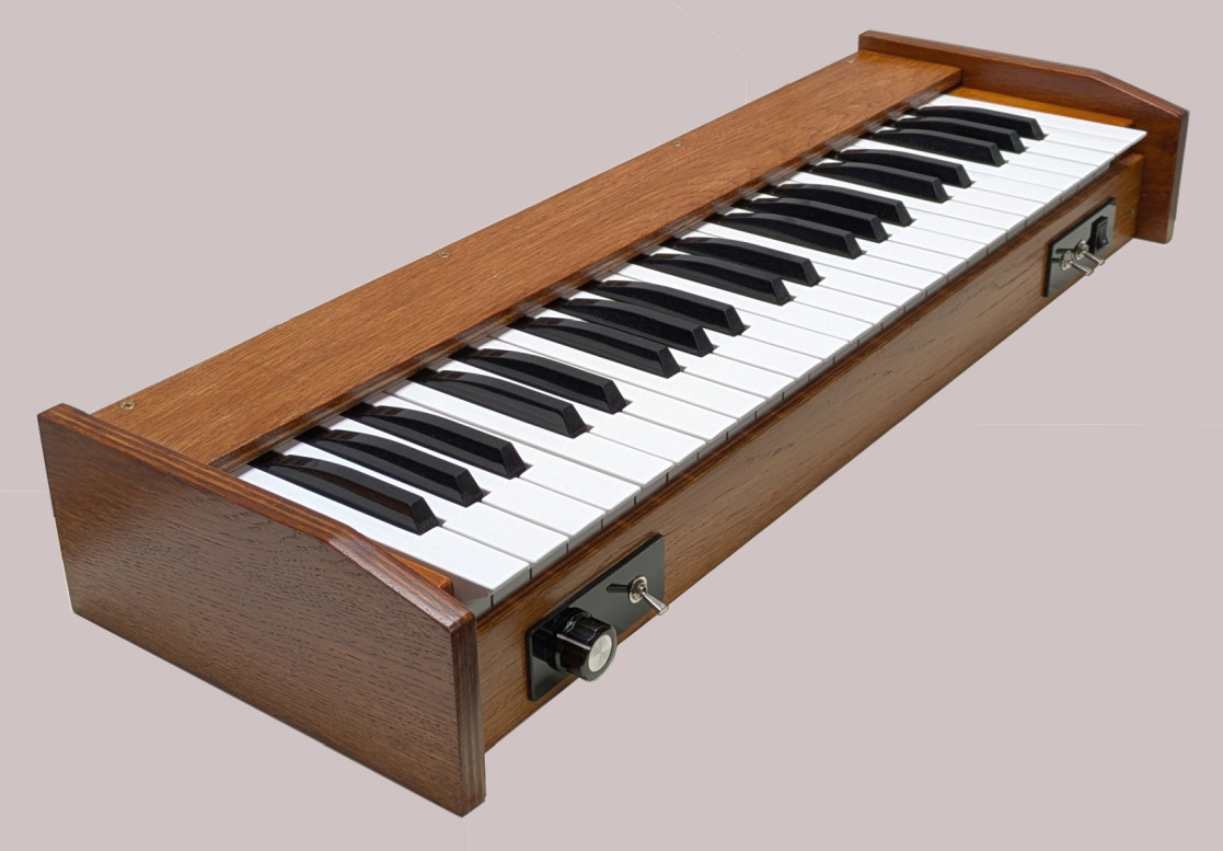
this alternative. Email me for details if you're interested. Player Controls The enclosure will have two small control panels on the front
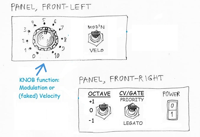
surface, below the keys, one on each side. The front-left panel will
have a knob (rotary pot) which may be used to control either
modulation or velocity level. Beside the knob is a switch to select
the function of the knob (i.e. modulation or velocity). If the knob is set to modulation, the "Pedal #1" function will
be velocity, and vice-versa.
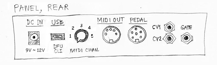
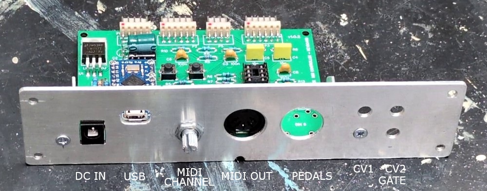
The rear panel provides external connections: DC power input (3 options), USB port on the Pro-Micro MCU, rotary switch to select the MIDI channel (one of 5), DIN-5 socket for MIDI OUT, DIN-6 socket for a "Pedal Board", and 3 x TS 3.5mm jacks for CV and Gate outputs. The "Pedal" socket has 2 analog inputs intended for Modulation (or Velocity) and Pitch-Bend, plus one digital input for a Hold/Sustain foot-switch. An extra digital input pin detects whether or not a pedal is connected.
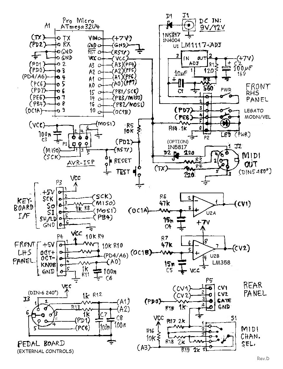
Since the Pro Micro MCU has pins for analog (PWM) output, it seemed obligatory to add a couple of CV outputs and a gate output, so that the keyboard can be used with a modular analog synthesizer, without needing a MIDI-to-CV adapter module. The pitch CV output (CV1) will be quantized into semitones. For CV1 and CV2 to cover the full 5V range, the MCU board must be powered via 'DC IN' (9~12V). The extra circuitry and program code needed to provide CV outputs is minimal. Here is the complete schematic of the proposed MCU board...
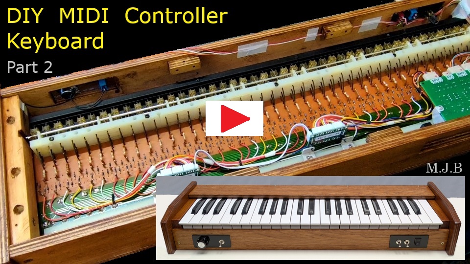
Note that 5V operation is possible via "power-over-MIDI" or via the USB port. If you don't need power-over-MIDI, remove the jumper JP1. The power switch is bypassed when using 5V power. DC IN voltage range is 8.5V to 13V to suit a 9V or 12V power supply. Raw Vin (to the MCU on-board 5V regulator) is fixed at about 7V using an LM1117 regulator IC. A heat-sink on the LM1117 is advisable where DC IN > 9V. The front panel connector pinouts are a bit mixed up because I changed my mind about the location of two switches. I moved the "Knob Function" switch (Modulation/Velocity) to the left side panel and the Octave Shift switch to the right side panel. As usual, my friend Jean-Pierre has done an elegant PCB layout for this project. If you intend to build a MIDI keyboard based on this design, Gerber files for PCB fabrication are available on request. Also, I have a few spare PCBs available. Email me for the postage charge to your country/state. 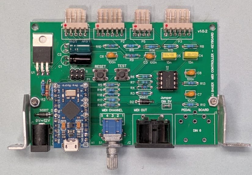 Micro-controller board mounted on rear connector panel. Video Clips on YouTube Here's a short video showing how the enclosure was built... (Part 1) 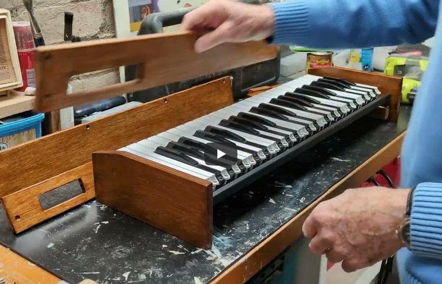 Part-2 shows making and fitting the control panels, rear connector panel with micro-controller board, and wiring the whole thing together...
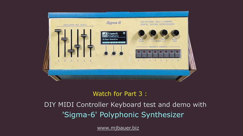
Part 3 (coming soon) will demonstrate the keyboard controlling a Sigma-6 Poly synth
___ MIDI Controller Operation The keyboard operates in the same manner regardless of the position of the Legato on/off switch. However, when the switch is moved to 'LEGATO' a MIDI 'Legato ON' message (CC68 + 127) is transmitted. When the switch is moved back to the normal position, a 'Legato OFF' message (CC68 + 0) is transmitted. It is assumed that the attached synthesizer complies with the MIDI Specification for legato mode. CV/Gate Operation -- Note Priority With the Legato switch off (open), the keyboard functions in a mode termed "Last-Note Priority", whereby the CV1 and Gate outputs respond to the most recent note keyed. The firmware will have a build option to implement an alternative keying mode, "High-Note Priority", whereby the CV and Gate outputs respond only to the highest note keyed when there is more than one key pressed. The intent here is for the CV and Gate outputs to follow the melody line being played, as far as practicable, on the assumption that the melody notes are higher than those in the accompanyment. CV/Gate Operation -- Legato With the Legato switch in the ON position, the keyboard operates as follows... A key press results in the Gate output being activated only if there are no other keys held pressed. In any case, regardless of any other keys being held pressed, a new key press results in the CV1 output (pitch) being set according to the newly keyed note. A key release results in the CV1 output (pitch) being set according to the key which caused the Gate output to be last activated. A key release results in the Gate output being negated if the released key was the only one pressed. Note: The 'Octave Shift' switch has no effect in CV/Gate operation. ...Firmware Download firmware package here The firmware package includes source code to compile and upload the program using Arduino IDE software on your PC. The "Firmware Build Options" (#defines) in the program code are meant to be edited to suit user preferences and hardware configuration. Note that cheap 'Pro Micro' board clones typically have the Arduino Leonardo bootloader installed in the MCU instead of the genuine Sparkfun Pro Micro bootloader. If using a clone, simply select the board 'Arduino Leonardo' in the IDE, if it is not already detected automatically. The Leonardo board I/O pin assignments and Arduino library functions are compatible with the Pro Micro, at least for this project. If you prefer, you can import the genuine Sparkfun board package into Arduino. Follow instructions on Sparkfun's Pro Micro web page. However, when I tried this, I could not get the USB-serial facility to work. ___ |
|
|
Thanks for taking an interest in this project. Feel free to send comments and queries...
Last update: 23-JAN-2026 |
 ...
...